


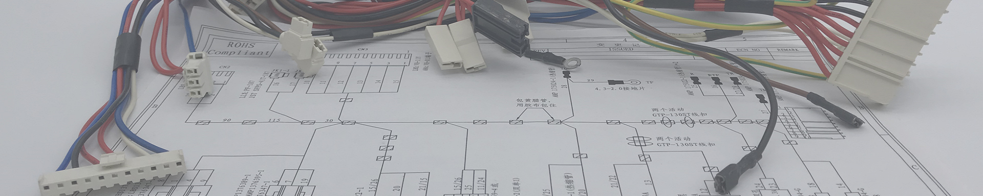
Custom Automotive Interior Electrical Systems: LED Lighting, Sensor, and Control Wire Harnesses Built to Your Cabin Layout
2026-09-04 11:30Custom Automotive Interior Electrical Systems: LED Lighting, Sensor, and Control Wire Harnesses Built to Your Cabin Layout
An RV converter in Germany emailed us last winter. His interior lighting harness supplier had shipped three SKUs in the wrong keyway. The ambient LED strip was drawing 1.2 A through a 22 AWG pair that was actually 24 AWG with a thick jacket painted to look like 22. After two weeks of warm-up, the jacket got tacky and started transferring brown residue onto the headliner. He asked if we could rebuild the harness, this time with the right wire, the right connector, and a print that matched his revised trim layout.
We could. It took us a week. That is more or less what this whole article is about — what goes into a custom automotive interior wire harness, and where most suppliers cut corners that you only find out about six months after delivery.
What this article covers:
The three subsystems that make up an interior harness: lighting, sensors, and control
LED dimming protocols, what each one actually requires on the wire side
Sensor harness design: from the ADAS camera pigtail to the seat occupancy mat
CAN, LIN, and the new ones — which bus fits which sensor, and why it matters for the harness
Wire and connector choices for the cabin environment (heat, smell, low outgassing)
EMC, ground loops, and the dimmer-buzz problem
How we build an interior harness, what we test, and what we will not ship
Common failures we see from other suppliers
A spec template you can copy into your next RFQ
Table of Contents
What an interior harness actually is
Walk into any car plant and ask an engineer to point at the "interior harness." He will probably wave his hand vaguely at the dashboard and the A-pillar. The thing is, there is no single interior harness. There are six to fifteen separate sub-harnesses, each one a custom build, and they are designed and assembled by different teams.
An interior harness is the wiring that lives behind the dashboard, in the headliner, in the door panels, under the seats, and in the center console. It is the wiring that does not see engine heat, brake fluid, or wheel-well gravel. That should make it easy, but it doesn't. The cabin is its own hostile environment: it gets to 90 °C in a parked car in summer, it gets condensation in winter, and it is the only place the driver can smell outgassing.
For an OEM or tier-one supplier, the interior harness is also the part of the wiring system that changes the most often. New display size, new ambient lighting pattern, new sensor, new trim level. Most of the engineering change orders on a car program touch the interior harness first.
So when a customer comes to us for a custom automotive interior wiring harness, they are usually not asking for a brand new design from scratch. They are asking us to match an existing harness, fix a problem with it, or build a variant of it for a low-volume program like a special edition, an RV, a coachbuilt, or a retrofit.
The three subsystems: lighting, sensors, control
When we look at any interior harness drawing, we sort the circuits into three buckets. This is how we think about the design and how we build it on the floor.
| Subsystem | What it powers | Typical current per circuit | Signal type | Failure mode we watch for |
|---|---|---|---|---|
| LED lighting harness | Map lights, dome lights, ambient strips, footwell lights, vanity mirrors, puddle lamps, RGB accent | 0.05 – 2 A | PWM, 0–10 V, LIN, CAN, or simple switched | Voltage drop over long runs, connector hot-spotting, jacket outgassing, LED color shift |
| Sensor harness | Seat occupancy, cabin air quality, light/rain sensor, ADAS camera pigtail, hands-free kick sensor, gesture module, humidity sensor | 0.01 – 0.5 A | Analog (0–5 V, 4–20 mA), LIN, CAN, LVDS, FPD-Link, I2C | Shield termination, ground reference, EMI from adjacent power circuits, connector pin alignment |
| Control harness | HVAC box, BCM pigtails, infotainment LVDS, steering wheel switches, window/lock switches, gear selector, EPB, antenna | 0.1 – 15 A | CAN, LIN, FlexRay, Ethernet 100BASE-T1, discrete | Bus termination, stub length, common-mode choke, power-on inrush |
A modern premium car can have more than 80 separate interior harness assemblies. An entry-level car might have 30. A coachbuilt or RV might have 12 sub-harnesses, each one doing a job the production car would have split into two or three.
LED lighting harness: voltage drop and dimming protocols
LEDs are the part of the interior harness where people cheap out most often, because the loads are small and the wires look like they can be anything. Then the customer opens a warranty claim twelve months later because the footwell light is yellow instead of white, and the ambient strip has a dark patch on the far end.
Two things cause this: voltage drop, and a dimming protocol the wire was not designed for.
Voltage drop. A 24 AWG copper pair will lose about 0.4 V over 5 m at 1 A. That is not the end of the world for a 12 V bulb, but for an LED with a forward voltage of 3.0 V and a driver set to 2.85 V, that is the difference between full brightness and a noticeable yellow or warm shift. For a 2 A RGB strip on a 6 m run, you need at least 20 AWG, and you need to know the total current, including the white channel, not just the average.
Dimming protocols. The same LED strip can be dimmed five different ways, and the harness changes for each. Here is the comparison we use on the floor:
| Protocol | Wire count to LED | Frequency / voltage | What the harness has to handle | Common gotcha |
|---|---|---|---|---|
| Simple switch (on/off only) | 2 | DC 12 V or 24 V | Just current. Nothing special. | Often paired with a 1 A fuse. If the load is 2 A, the fuse never blows but the connector runs hot. |
| PWM dimming (low-side, 200 Hz typical) | 2 | 200 Hz – 1 kHz, 12 V switched | Twisted pair recommended if the LED cable runs next to a radio antenna lead. No filtering required for most loads. | Whine at 200 Hz if the switching supply is poorly designed. Some people hear it, some do not. |
| 0–10 V analog dimming | 4–5 (power + 0–10 V signal) | 0–10 V DC control | Shielded signal pair, drain wire grounded at controller only. Separate from power pair to avoid ground loops. | If the drain is grounded at both ends, dim range collapses and the strip flickers at low levels. |
| DALI / DALI-2 | 2 (bus-powered) | 16 V DC, 1.5 kbit/s | Polarity-insensitive bus, but pairs must be twisted and routed away from noisy power cables. | Bus devices need addressing. If you build a harness without programming the addresses, the customer gets a bus full of unconfigured LEDs. |
| LIN bus (RGB LED modules) | 2 or 3 | LIN 19.2 kbit/s, 12 V supply | Twisted pair, 1 nF capacitor on each node to ground. Master termination 30 Ω, slave 1 kΩ pull-up. | Stub length matters. Anything over 200 mm and you get bit errors on the bus, especially at cold start when supply voltage is low. |
| CAN-FD (addressable LED drivers) | 2 (bus) + 2 (power) or 4 shared | CAN-FD up to 2 Mbit/s, 12 V supply | Twisted pair, 120 Ω termination at both ends, common-mode choke at BCM exit. | If you use the same pair for power and data, the voltage drop shifts the bus recessive level. Car stops talking to itself. |
Most of the dimmer-buzz problems we see on a returned harness come from a 0–10 V signal pair that was twisted with the power pair at the connector, instead of being run as a separate bundle. The fix is trivial. The cost of doing it right the first time is trivial. The cost of doing it wrong and reworking the harness is not trivial.
Sensor harness: the easy part to get wrong
Sensors in the cabin are small. Their current draw is small. The wire can be 26 AWG or even 28 AWG. It feels like it should be the easiest part of the harness to build. It is the part we see misbuilt most often, because the failure shows up as a fault code, not as a dead light.
A short list of interior sensors we build harnesses for:
| Sensor | Location in cabin | Signal type | Wire | Connector | What the harness has to get right |
|---|---|---|---|---|---|
| Seat occupancy mat | Under seat trim | Analog (resistance change), or LIN | Shielded 2-conductor + drain | 4-pin Mini-USB style or 3-pin sealed | Drain grounded at ECU end only. Mat itself is capacitive, so the harness adds capacitance to ground. Get the drain wrong and the ECU sees a phantom passenger. |
| Cabin humidity / fog sensor | Behind rear-view mirror | LIN or analog | 3-conductor, twisted | 3-pin sealed (Sumitomo HM or Yazaki 58) | Must be sealed against windshield fog ingress. We do a 50 kPa vacuum leak test on every pigtail that goes behind the glass. |
| Light / rain sensor | Windshield, near mirror mount | LIN | 3-conductor, twisted, 0.35 mm² | 3-pin sealed | Cable length is fixed. The sensor is calibrated to the cable capacitance. Change the length by 100 mm and the auto-wipers misbehave. |
| ADAS front camera pigtail | Top of windshield, behind mirror | LVDS or FPD-Link III, coax or twisted pair | 100 Ω differential pair, shielded, 50 Ω controlled impedance | Mini-FAKRA or HSD (high-speed data) | Bend radius 4× cable OD minimum. A 90° bend at the connector kills the link. We do TDR tests on every high-speed pigtail we build. |
| Hands-free kick sensor (power sliding door) | Behind rear bumper trim | Capacitive, analog front-end | 2-conductor + drain, shielded | 2-pin sealed | Drain ground reference must be at the BCM, not at the sensor. Otherwise the sensor fires when the door is closed even though nobody is there. |
| Steering wheel angle sensor | Behind airbag / clock spring | CAN or FlexRay | Twisted pair, 120 Ω terminated at sensor and BCM | Clock spring integrated connector | The clock spring is a flex cable, not a wire harness, but the harness connects to it. We will not build a harness that bypasses the clock spring spec. |
The point of this table is that the wire, the connector, the length, the drain, and the bend radius are all part of the sensor's calibration. If you change any of them without telling the sensor manufacturer, the sensor does not work the way it was tested.
Control harness: CAN, LIN, and the new kids
Most interior control modules in a current production car talk to each other on CAN or LIN. Some of them have moved to CAN-FD. A few premium programs are starting to use automotive Ethernet (100BASE-T1 or 1000BASE-T1) for high-bandwidth items like the infotainment display and the ADAS domain controller. Here is how the bus choice drives the harness design.
| Bus | Bit rate | Wire type in our harnesses | Termination | Where we see it inside the cabin | Notes from the build floor |
|---|---|---|---|---|---|
| LIN 2.x | 19.2 kbit/s | 0.35 mm² unshielded twisted pair, or 0.22 mm² for low-vibration routes | Master 30 Ω, slave 1 kΩ pull-up, no termination resistor on slaves | Roof console, ambient lighting, seat switches, mirror adjust, HVAC blend door | If you build a harness with the LIN pair tied to the wrong ground node, the bus sleeps when the BCM sleeps and the master never wakes up. |
| CAN 2.0B | 500 kbit/s (typical cabin) up to 1 Mbit/s | 0.35 mm² or 0.5 mm² unshielded twisted pair, optional foil + braid for high-EMI routes | 120 Ω at each end of the bus, never in the middle | BCM, HVAC, instrument cluster, door modules, seat modules, gateway | If a stub is longer than 1/10 of the bit time at the bus speed, you will see reflection errors. For 500 kbit/s that is about 6 m max, in practice we keep stubs under 0.5 m. |
| CAN-FD | 2 Mbit/s (data phase), 500 kbit/s (arbitration) | 0.35 mm² twisted pair, mandatory twist 33 turns per meter | 120 Ω split termination (60 Ω + 60 Ω with 4.7 nF to ground) preferred | ADAS domain controller, gateway, infotainment head unit | Old 120 Ω resistors cause ringing. We spec split termination now for every CAN-FD build. |
| FlexRay | 10 Mbit/s | 0.35 mm² twisted pair, 100 Ω differential | 100 Ω at each end, no stubs allowed | Legacy premium programs, some chassis control modules | Most new programs have moved off FlexRay. We still build FlexRay harnesses for active programs, but we do not see new RFQs. |
| Automotive Ethernet 100BASE-T1 | 100 Mbit/s | 0.35 mm² UTP, 100 Ω differential, controlled impedance | No bus termination at nodes. Inline coupling on the PHY side. | Infotainment, ADAS sensor fusion, digital cockpit, some HVAC touch panels | Routing rules are similar to LVDS. Bend radius and connector pin assignment are the most common failure points. |
If you are building a custom automotive interior wire harness for a new program, the bus choice is made by the EE team. What we bring to the table is the harness implementation: twist rate, stub length, termination resistor placement, common-mode choke, and routing through the harness to keep the bus clean.
Wire and insulation: the cabin is not the same as the engine bay
Wire in the engine bay has to survive 150 °C, oil, and vibration. Wire in the cabin has different problems.
| Wire spec | Where we use it in the cabin | Why | What we will not use |
|---|---|---|---|
| AVSS / AVSSH (thin-wall, 85 °C) | General low-current interior circuits, harness backbone | Low outgassing, low odor, easy to strip | PVC. Outgases HCl at failure temperatures, smells bad in a closed cabin, and is banned by most OEMs. |
| AESSX (cross-linked polyethylene, 105 °C) | Higher temperature zones: roof console, infotainment, EV battery-adjacent cabin modules | Better heat resistance, more abrasion-tolerant than AVSS | Standard PVC. Same problem as above, plus it ages faster under heat cycling. |
| Silicone-jacketed wire | RGB ambient strips, decorative lighting with high flexibility demand | Stays flexible from −40 °C to 200 °C. The only choice if the harness is on a moving door hinge. | "Silicone-coated" wire that turns out to be silicone over PVC. Test every spool with a cross-section and a strip test. |
| Shielded twisted pair (foil + drain, optional braid) | Sensor signals, LVDS, CAN-FD, Ethernet | EMI rejection, controlled impedance | Unshielded wire in a noisy cabin environment. A 12 V PWM dimmer line sitting next to an ADAS camera pigtail will leak noise into the camera even with a good shield on the camera wire. |
| Bonded parallel pair (cross-web) | CAN backbone, LIN backbone | Holds twist rate through the entire harness. If you do not bond the pair, the twist rate varies and so does the impedance. | Loose twisted pair where the customer has not specified a twist rate. We default to 33 turns per meter unless the customer says otherwise. |
Outgassing is the thing most first-time interior harness buyers forget about. The cabin is a closed space. If the wire jacket outgases plasticizer, the windshield fogs, the headliner gets sticky, and the customer notices. Most OEM cabin specs call for low-outgassing materials (VDA 270, Toyota TSM 7600G, or equivalent). We build to those by default on every interior harness unless the customer says otherwise.
Connectors inside the cabin
Connectors in the cabin are mostly unsealed. The cabin is not watertight, but it is not the engine bay either. The connector families we use most often:
Yazaki 58, Sumitomo HM, JST MX — sealed interior connectors, 0.64 mm terminals, mostly behind the IP and in doors
JST PH / XH / EH — unsealed, for PCBs and small modules, same families we use in industrial harnesses
Mini-FAKRA and HSD — high-speed data: camera, display, Ethernet
TE MQS (Micro Quadlock) — unsealed, low-current, body control modules
AMPSEAL 16 — sealed, when the harness passes through a grommet into a wet zone (door to mirror, sliding door kick sensor)
USB-C, HDMI, DisplayPort pigtails — for infotainment breakout harnesses
Two practical things on connectors. First, the terminal matters more than the housing. We have seen ten different "Yazaki 58" housings on the market, and four of them are knockoffs. The terminal crimp on a genuine Yazaki terminal is not the same as a no-name terminal, even if both fit the housing. We buy from authorized distributors and we keep a sample of every lot we use.
Second, pin assignment and wire color are part of the connector spec, not the harness spec. If you have a 4-pin connector and you put two of the wires on the same color, you will be back at the bench re-doing it when the customer's EE wants to swap polarity. We label every cavity on the print, and we double-check against the connector spec on every build.
EMC, ground loops, and why your dimmer hums
Half of the EMC problems we see in interior harnesses are not caused by the harness. They are caused by the chassis ground. The BCM sits at a different ground potential than the roof console, by about 30 mV in some cars. That is enough to inject hum into a high-impedance analog signal, especially an audio signal.
Three rules we apply on every interior harness build:
Ground returns travel with their own signal. We do not share a ground wire between two unrelated circuits, even if the customer drawing says it is OK. The 10 cents you save on a shared ground is not worth the debugging time later.
Shield drain is grounded at one end only. Low-frequency signals (analog, 0–10 V, audio): drain at the receiver. High-frequency signals (LVDS, Ethernet, FPD-Link): drain at both ends with a 1 MΩ DC block. Customer drawing says otherwise? We will ask first.
Noisy and quiet circuits do not share a bundle. A PWM dimmer pair and an ADAS camera pigtail should never be in the same wrap. If they have to cross, they cross at 90° and they are separated by at least 25 mm.
The dimmer hum, by the way, is almost always a ground loop. Either the LED driver ground is on a different chassis point than the BCM, or the 0–10 V control pair drain is grounded at both ends. Lift the drain at one end. The hum usually goes away.
How we build an interior harness
For an interior harness, the build looks like this. The numbers are not magic, they are the process we have refined over the last ten years of doing this.
DFM review. We get the customer's drawing, the BOM, and any reference photos. We flag issues in the first 48 hours. Free.
DFM report. We send a one-page DFM with every concern: wire gauge vs. current, bend radius, connector strain relief, EMC routing, label placement. The customer accepts or we adjust before we cut any wire.
Sample build (5–10 pcs). We build a first batch on the bench, using the actual wire and connectors. We do a continuity test, a pull-force test, and a hipot test on every sample. We send photos and a sample to the customer before production.
Customer sample approval. Customer fits the sample in the vehicle, checks routing, confirms connector seating. We freeze the build instructions.
Production cut and crimp. Cut list comes from the DFM, not from re-measuring. Every crimp is on a dedicated applicator, not a hand tool. We log applicator ID on every build sheet.
Sub-assembly. We build the harness in sections: door, IP, headliner, console, seat. Each section is continuity-tested before the next section is joined.
Final assembly and 100% electrical test. Continuity on every pin, hipot on every circuit, plus a fault check (short to ground, short to power) on every pin pair. We do not ship a harness that has not passed 100% electrical test.
Final visual and pack-out. We label every connector, every branch, and every anchor point. We pack in batches of 25, 50, or whatever the customer specifies.
Typical lead time for a new interior harness: 7 to 10 days for samples, 15 to 25 days for production after sample approval. For an existing harness with no design changes, we can turn production in 10 to 15 days.
QC: what we test before a harness leaves the floor
Every interior harness we ship has been through the following matrix. We can adjust the matrix to match your spec, but the minimum we run is this:
| Test | Equipment | What it catches | Sample rate |
|---|---|---|---|
| Continuity | Automatic cable tester (Cirrus, or comparable) | Open circuits, mis-pinned connectors, wrong wire | 100% on every unit |
| Hi-pot (dielectric withstand) | Associated Research or comparable, 500 V or 1500 V DC depending on circuit | Insulation breakdown, pinched jacket, conductor near short | 100% on every unit, 1 s hold |
| Insulation resistance | Same hipot tester, IR mode, 500 V DC | Moisture ingress, jacket defect, contamination | 100% on every unit, ≥ 100 MΩ pass |
| Pull-force (crimp) | Mecmesin or comparable force gauge | Under-crimped terminals, wrong applicator, wrong terminal | 5 samples per batch or per 500 pcs, whichever is greater |
| Connector seating | Mechanical gauge, mating cycle counter | Half-seated TPA, mis-locked connector | 100% on every unit (visual + tactile) |
| Shield continuity and isolation | Low-voltage continuity + TDR for high-speed pairs | Open shield, shield short to conductor, impedance break on LVDS / Ethernet | 100% on shielded pairs, TDR on every high-speed pigtail |
| Outgassing / odor | Sample strip test, VDA 270 if specified | Plasticizer migration, jacket defect, supplier lot change | Per wire lot, retained sample |
On the floor, every build has a 100% electrical test. The hipot and continuity testers are calibrated monthly. We do not skip the hipot. We have shipped a lot of bad harnesses in our early years, and every one of them was caught by either a hipot test that was not run, or a pull-force test that was skipped because the operator thought "this crimp looks fine." A pull-force test is 30 seconds per terminal. The cost of skipping it is the customer's warranty claim.
Failures we fix from other suppliers
Some of the patterns we have seen in returned or replacement interior harnesses over the last few years:
Wire marked 22 AWG, measured 24 AWG. This was the German RV customer at the top of this article. The jacket was a thick PVC with a printed "22 AWG" legend, but the copper was 24 AWG. We measure the conductor cross-section on every new wire lot.
Jacket outgassing onto headliner. PVC or low-grade TPE jacket in a closed cabin, parked in the sun. The plasticizer migrates and leaves a brown film. We default to AVSS / AESSX unless the customer specifies otherwise.
Connector keyway wrong by one position. Two-pin offset on a six-pin connector. The mating connector was a different supplier's catalog number. We build against the customer-supplied connector sample, not the catalog drawing.
Shield drain grounded at both ends. Common in low-frequency signal harnesses (0–10 V, audio, analog sensor). Causes hum, oscillation, or sensor misread. We terminate the drain at one end only, per the customer's spec, and we flag it in the DFM if the spec is unclear.
Stub length too long on CAN. Adding a node to a CAN bus and tapping into the nearest backbone. The stub length was 1.5 m, which is fine for 125 kbit/s but not for 500 kbit/s. We pull the node out to a proper stub length or we add a repeater.
Bonded pair that is not actually bonded. The wire was specified as "bonded pair, 33 turns per meter" but the supplier delivered a loose twisted pair with maybe 15 turns per meter. We buy bonded pair from manufacturers that publish the spec and we verify the twist count on the first spool of every new lot.
RFQ spec template
If you are putting together an RFQ for a custom automotive interior wire harness, this is the data we need to give you a real quote. We can quote from a drawing alone, but the fewer assumptions we make, the more accurate the number.
| Item | What to send | Why we need it |
|---|---|---|
| Drawing or schematic | PDF or STEP, with all connectors labeled | Source of truth for wire count, gauge, and routing |
| BOM or connector list | Part numbers, manufacturer, keying, seal/unseal | Lead time on connectors is usually the long pole. We need to know the exact part, not "JST PH equivalent." |
| Wire list | AWG or mm², insulation type, color, twisted/bonded, shielded | If you have a wire spec, send it. If you do not, we will spec it for you. |
| Quantity per SKU | Per batch, per year, total over program life | Volume drives connector tooling amortization, wire spool buy, and our ECO policy |
| Vehicle or program info | Make, model, year, market (EU, US, JP, CN), trim level | Drives compliance: RoHS, REACH, ELV, FMVSS, ECE R10 for EMI, low-outgassing spec |
| Service environment | Temperature range, humidity, condensation, vibration | Drives material choice: AVSS vs AESSX, sealed vs unsealed connector, jacket material |
| Sample quantity and lead time expectation | Sample qty, sample date, production start, total volume | We plan our build schedule around this |
| Quality requirements | PPAP, IMDS, IATF 16949, customer-specific docs | Document pack is part of the cost |
Send the spec to our RFQ inbox. We will come back with a one-page DFM and a quote within 48 hours, usually faster.
Why work with us
We have been building wire harnesses in Xiamen for over ten years. We do industrial, medical, audio, energy, and automotive. The interior harness work is a smaller part of our book than the engine bay, but it is the part that requires the most iteration with the customer's EE team, and that is the work we like.
What you get from us, that you might not get from a larger tier-one:
DFM review in 48 hours, free. No charge for the first review, no charge for the second, no charge for the call to discuss the third.
5-day ECO turnaround. Connector change, wire spec change, label change. We turn engineering change orders in five working days or we tell you why we cannot.
Sample build before production. You get a real harness in your hand before we cut production wire.
Single point of contact. One project engineer, one account manager. The same person answers the phone when you call back in two weeks.
Multi-variant BOM management. If your program has 6 trim levels and 3 regional variants, we hold the variant matrix and ship the right harness for the right vehicle, not a single SKU and a "best effort" at the connector.
100% electrical test on every unit. Continuity and hipot on every harness. Pull force per batch. Document pack with every shipment.
Low-volume friendly. We do small-batch interior harnesses for RVs, coachbuilders, and aftermarket accessory makers. MOQ for a new program is 100 pcs. We have shipped batches of 50.
We will not be the cheapest supplier you talk to. We will be the supplier that delivers a harness that fits on the first try, that passes your incoming inspection, and that does not show up on a warranty claim six months later.
Frequently Asked Questions
Q1: What is the minimum order quantity for a custom automotive interior wire harness?
For a new program, our MOQ is 100 pcs. For an existing program with a frozen build, we will produce to your forecast with no MOQ on re-orders. We have shipped prototype batches of 10 to 20 pcs for fit-check purposes.
Q2: Can you build to our internal drawing format, or do you need a customer-specific template?
Both. We work with customer-native drawings (CATIA, Mentor, E3, Zuken) and we can rebuild the harness drawing in our own format if you want us to. The native drawing is the source of truth. The rebuild is for our internal build instruction.
Q3: Do you handle IMDS and PPAP documentation?
Yes. We are IATF 16949 certified and we submit IMDS entries for every new wire, connector, and material we introduce. PPAP level 3 is standard; level 5 is available on request.
Q4: What is the typical lead time from drawing approval to first production batch?
For a new program, 25 to 35 days: 7 to 10 days for samples, 18 to 25 days for production after sample approval. For repeat orders on a frozen build, 10 to 15 days. Connector lead time is usually the constraint, especially for the FAKRA and HSD families.
Q5: Can you build harnesses with automotive Ethernet (100BASE-T1 or 1000BASE-T1)?
Yes. We build 100BASE-T1 pigtails for infotainment and ADAS sensor fusion. We do TDR verification on every Ethernet pair. For 1000BASE-T1, we are working with a few programs now, lead time is similar to FPD-Link.
Q6: How do you handle regional variants (EU vs US vs JP)?
We hold a variant matrix per program. You send us the build sheet for the order (vehicle VIN, trim, region) and we ship the matching harness. We do not build one harness and "make it work" with a field-fix kit.
Q7: Can you take over an existing harness from a supplier that is no longer performing?
Yes, this is a lot of what we do. Send us samples of the current harness, the original drawing if you have it, and a list of the issues you are seeing. We will do a tear-down report, identify the failure modes, and propose a fixed harness. Typical timeline is 2 to 3 weeks from sample receipt to first batch of the fixed design.
Start Your Custom Interior Harness Project
Send us your drawing, your BOM, and the volume you need. We will come back with a DFM and a quote, usually within 48 hours. If you do not have a drawing yet, send us the vehicle spec, the list of features you need, and a few reference photos. We will help you scope it.
Email: [sales5@xmkehan.com]
Typical response time: 24 hours, Monday to Friday
SEO Keywords: custom automotive interior wiring harness, automotive interior wire harness manufacturer, custom car interior harness, automotive LED lighting harness, car interior LED wire harness, RGB ambient lighting harness, automotive sensor wire harness, cabin sensor harness, ADAS camera pigtail harness, automotive CAN bus harness, LIN bus interior harness, automotive Ethernet 100BASE-T1 harness, OEM interior harness, custom automotive control harness, low outgassing automotive wire, automotive LVDS display harness, IATF 16949 wire harness supplier, automotive wiring harness China, custom RV interior harness, coachbuilt wiring harness, aftermarket interior harness.