
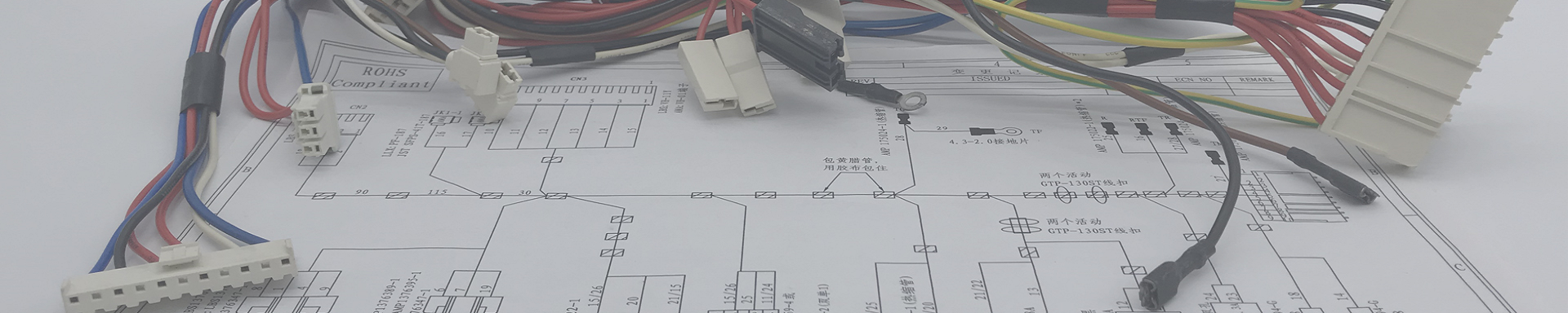
Explanation of Wire Harness Production Process
2026-03-17 16:00I. Wire Cutting: Precise Length Determination, the Perfect Start
Wire cutting is the first step in wire harness production, and its accuracy directly affects the quality of all subsequent processes.
1.1 Preparation
Equipment inspection: Confirm that the automatic wire cutting machine operates normally, with no abnormal noise or vibration
Blade inspection: Ensure cutting blades are sharp with no nicks, and the blade edge is flat and undamaged
Workbench cleaning: Remove debris, ensuring no leftover wire scraps or oil stains from previous production
ESD protection: For sensitive wires, confirm that electrostatic discharge protection measures are in place
1.2 Setup and Cutting Operation
Drawing confirmation: Carefully review engineering drawings or work instructions to confirm wire specifications (type, AWG, color, insulation material)
Equipment setup: Set cutting length, stripping length (if required), wire feeding speed, and other parameters according to wire specifications
First article inspection: Test cut 3-5 pieces, measure dimensions with calipers or steel rulers, confirm within tolerance range
Mass production: Beginbatch cutting only after first article passes inspection
1.3 Key Technical Requirements
| Control Item | Standard Requirement | Inspection Method |
|---|---|---|
| Dimensional Accuracy | Length tolerance must meet drawing requirements (typically ±2-5mm) | Measure with steel ruler or calipers |
| Cut Quality | Cut ends flat and even, no angled cuts, burrs, or wire pulls | Visual inspection, magnifying glass if needed |
| Wire Appearance | No scratches, indentations, or insulation damage | Visual inspection under adequate lighting |
| Labeling Management | Bundle in groups of 50 or 100 pieces, label with wire gauge, length, production date | Verify label information |
1.4 Common Cutting Defects and Prevention
| Defect Type | Cause | Prevention Measures |
|---|---|---|
| Length Out of Tolerance | Slipping feed wheel, incorrect parameter settings | Clean feed wheels regularly, mandatory first article inspection |
| Angled Cut | Worn blades, improper installation | Replace blades regularly, check blade installation |
| Insulation Scratch | Burrs in feed channel, excessive tension | Clean feed channel, adjust tension |

II. Grommet Installation: Fundamental Protection, Attention to Detail
Grommets protect wire harness branch points or terminal roots, preventing mechanical damage and stress concentration.
2.1 Operation Steps
Confirm grommet specification: Select the correct grommet type according to drawing requirements
Insertion direction: Insert the end of the wire that will receive a terminal through the grommet, ensuring the small end (or specified direction) faces downward as shown in the drawing
Pre-positioning: Temporarily position the grommet on the wire at an appropriate location; final position will be adjusted after terminal crimping
2.2 Quality Control Points
Correct grommet specification, no cracks or deformation
Correct insertion direction, no reverse installation
Grommet remains in position without shifting or falling off during subsequent processes
III. Wire Stripping: Precise Removal, Undamaged Conductors
Wire stripping removes the insulation from the wire end, exposing the metal conductor for terminal crimping.
3.1 Preparation
Inspect stripper condition: Confirm equipment operates normally, blades are sharp and undamaged
Clean workbench: Ensure no debris to avoid contaminating wire conductors
3.2 Setup and Operation
Parameter setting: Set stripping length and blade depth according to wire specifications (diameter, insulation thickness)
First article test: Test strip 3-5 pieces, check stripping length and conductor condition
Mass production: Begin batch production only after first article passes inspection
3.3 Stripping Length Reference
Stripping length is generally determined by the terminal crimp barrel length, with common calculation formulas:
Conductor cross-section ≤ 1mm²: Stripping length = Crimp barrel length + 1mm
Conductor cross-section 1-10mm²: Stripping length = Crimp barrel length + 2mm
Conductor cross-section ≥ 10mm²: Stripping length = Crimp barrel length + 2-3mm
3.4 Key Technical Requirements
| Control Item | Standard Requirement | Inspection Method |
|---|---|---|
| Stripping Length | Within drawing tolerance (typically ±0.5-1mm) | Measure with calipers |
| Conductor Integrity | No broken or damaged strands, strand breakage rate ≤8% | Visual inspection, magnifying glass if needed |
| Cut Quality | Cut end smooth, no burrs or residual insulation | Visual inspection |
| Insulation End | Insulation cut clean, no tearing | Visual inspection |
3.5 Common Stripping Defects and Solutions
| Defect Type | Cause | Corrective Action |
|---|---|---|
| Broken Strands | Blade cutting too deep | Adjust blade depth, retest |
| Residual Insulation | Blade cutting too shallow | Adjust blade depth, retest |
| Stripping Length Out of Tolerance | Improper positioning | Reset parameters, verify with first article |
| Oxidized/Discolored Conductors | Contaminated blades, improper wire storage | Replace blades, check material storage |

IV. Terminal Crimping: Core Process, Quality Lifeline
Terminal crimping is the critical process that forms a permanent connection between the wire and terminal through mechanical pressure, directly determining the wire harness electrical performance and mechanical strength.
4.1 Preparation
Equipment inspection: Confirm crimping machine operates normally, air pressure stable (for pneumatic equipment)
Die inspection: Confirm crimping dies match the terminal type, with no wear or damage
Workbench cleaning: Remove debris, prepare collection containers
4.2 Setup Operation
Professional technicians install and adjust dies, set crimp height or crimp force parameters
Test crimp 3-5 pieces for first article inspection:
Visual inspection of crimp appearance
Measure crimp height (using micrometer)
Perform pull force test (if required)
Mass production begins only after first article passes inspection
4.3 Terminal Fundamentals
| Terminal Type | Characteristics | Typical Applications |
|---|---|---|
| Open Barrel Terminal | Crimping barrel is U-shaped or V-shaped, open during crimping | General connections, easy to inspect |
| Closed Barrel Terminal | Crimping barrel is O-shaped, closed type, wraps around conductor after crimping | High reliability requirements, good vibration resistance |
| Pre-insulated Terminal | Includes insulation sleeve, no additional insulation needed after crimping | Appliances, control panel wiring |
| Sealed Terminal | Includes sealing ring, forms waterproof structure after crimping | Automotive, outdoor equipment |
4.4 Key Technical Requirements
| Control Item | Standard Requirement | Inspection Method |
|---|---|---|
| Crimp Height | Within terminal specification tolerance (typically ±0.05-0.1mm) | Measure with micrometer |
| Crimp Appearance | No over-crimping, under-crimping, wire strands fly off, terminal deformation, crimp cracks | Visual inspection, 20x magnifying glass |
| Bell Mouth | Appropriate bell mouth at crimp barrel entrance and exit | Visual inspection |
| Conductor Position | Conductors fully inside crimp barrel, visible at front end | Visual inspection |
| Insulation Position | Insulation located in insulation crimp area, properly compressed but not pierced | Visual inspection |
| Pull Force | Meets industry standards (e.g., LV214, USCAR) or customer requirements | Pull tester measurement |

4.5 Crimp Defect Reference
| Defect Type | Description | Cause | Consequence |
|---|---|---|---|
| Over-crimping | Excessive indentation, terminal deformation | Crimp height set too low | Conductor damage, reduced mechanical strength |
| Under-crimping | Insufficient indentation, terminal not fully deformed | Crimp height set too high | High contact resistance,容易 loosening |
| Wire Strands飞出 | Copper strands extending outside crimp area | Conductor not fully inserted, die wear | Short circuit risk |
| Crimp Offset | Indentation not centered | Improper terminal positioning, die wear | Uneven crimp force, poor reliability |
| Insulation Crimping | Insulation compressed into conductor crimp area | Stripping length too short | Increased contact resistance |
4.6 Safety Precautions
Never place hands in the die area during operation technician
For two-hand operated equipment, both buttons must be pressed simultaneously
Do not clean scrap or adjust dies while equipment is running
Stop immediately if abnormality is detected and report to
V. Connector Assembly: Precise Positioning, Reliable Locking
Insert the crimped terminals into the corresponding connector housings according to drawing requirements.
5.1 Operation Steps
Confirm connector housing type: Select the correct connector housing according to drawing
Check terminal locking mechanism: Confirm terminal barbs are intact
Insert wire: Align the crimped terminal with the corresponding cavity in the housing, push in with even force
Verify locking: Listen for a "click" or feel the lock, gently pull the wire to confirm it does not pull out
5.2 Key Technical Requirements
| Control Item | Standard Requirement | Inspection Method |
|---|---|---|
| Insertion Position | Must correspond one-to-one with drawing cavity requirements, no misalignment | Check against drawing |
| Locking Confirmation | Terminal fully locked, does not pull out with gentle tug | Gently pull wire to test |
| Terminal Orientation | Terminal barb direction correct, no reverse insertion | Visual inspection |
| Appearance Check | Housing no cracks, terminals not skewed | Visual inspection |
VI. Electrical Testing: Functional Verification, Quality Assurance
Electrical testing is the final defense ensuring wire harness functionality and the most critical part of wire harness testing.
6.1 Test Purpose
Verify circuit continuity: Confirm every line conducts correctly
Detect shorts: Confirm no unintended conduction between adjacent circuits
Verify insulation performance: Test insulation resistance and dielectric strength
6.2 Test Equipment
| Equipment Type | Function | Application Scenario |
|---|---|---|
| Continuity Tester | Detects open circuits, shorts | General wire harnesses, basic testing |
| Hi-Pot Tester | Tests insulation strength | High-voltage harnesses, safety requirements |
| Comprehensive Tester | Integrated continuity, hi-pot, resistance | Complex harnesses, high efficiency |
| Flying Probe Tester | Flexible testing, no fixtures required | Small batches, high mix |
6.3 Test Steps
Fixture connection: Properly connect the special use test fixture to the tester, secure to workbench with fixture clamp
Equipment self-check: Test with a known defective sample to confirm tester and fixture working properly
Product testing: Insert the test harness connectors into corresponding fixture sockets
Result judgment:
Observe tester indicator lights (typically green light indicates pass, red light or buzzer indicates fail)
Or read test results displayed on tester screen
5.Remove product: After testing, pull connector out parallel (do not pull at an angle)
6.4 Test Standards
| Test Item | Acceptance Criteria | Notes |
|---|---|---|
| Continuity Test | All Line conduction resistance less than set value (typically <1-5Ω) | Adjust based on length and wire gauge |
| Short Test | Resistance between adjacent circuits greater than set value (typically >10-100MΩ) | Ensure no shorts |
| Insulation Resistance | Resistance between wire-wire, wire-shield >100MΩ (500V DC) | Per customer requirements |
| Hi-Pot Test | Leakage current <5mA at specified voltage (e.g., 500-1500V AC/DC) | Per safety standards |

6.5 Precautions
After testing, self-check housing for scratches, terminals for skewing
If continuation electrical test failures occur, stop immediately and report to supervisor or QC
Strictly separate good and defective products, label clearly, place defective products in designated red area
Test probes are wear parts; replace every 3,000 insertions or as needed based on actual condition
Record and archive test data for quality traceability
VII. Harness Assembly: Integration into Finished Product, Neat and Organized
Bundle the tested branch harnesses together using tape or sleeving according to drawing requirements to form the final finished product.
7.1 Preparation
Install location pins on assembly fixture according to engineering drawing
Confirm location pin position dimensions are within drawing tolerance
7.2 Operation Steps
Secure harness: Place the tested branch harnesses on the fixture according to drawing requirements, hanging connectors on corresponding location pins
Position check: Confirm all branch positions are correct, no misalignment
Tape wrapping:
Start wrapping from the star position indicated on the fixture
Tape should overlap by at least 1/2 width
Maintain even tension, no wrinkling, no looseness
Stop at the end position indicated on the fixture
Sleeve installation: If corrugated tubing, braided sleeving, etc., are required, install according to drawing instructions
7.3 Key Technical Requirements
| Control Item | Standard Requirement | Inspection Method |
|---|---|---|
| Branch Position | All branch dimensions within drawing tolerance | Measure with steel ruler |
| Tape Wrapping | Overlap ≥1/2, even no wrinkles, at least one full overlap at start and end | Visual inspection |
| Sleeve Installation | Correct sleeve size, properly installed, no slippage | Visual inspection |
| Appearance | Harness neat, no crossing, no twisting | Visual inspection |
VIII. Dimensional Inspection: Comprehensive Verification, Ensuring Compliance
Perform comprehensive dimensional measurement on the assembled finished harness to confirm compliance with drawing requirements.
8.1 Operation Steps
Fixture preparation: Install location pins on inspection fixture according to engineering drawing, mark all dimensions and tolerance ranges on the fixture
Position harness: Place the assembled harness connectors on the corresponding location pins
Straighten and measure: Gently straighten the harness, measure all dimensions with steel ruler or tape measure
Result judgment: Pass if all dimensions are within tolerance; fail otherwise
8.2 Inspection Items
| Inspection Item | Description |
|---|---|
| Main Trunk Length | Length from first branch point to last branch point on main harness |
| Branch Length | Length from main trunk split point to connector根部 for each branch |
| Connector Position | Positioning dimensions of each connector on the fixture |
| Stripping Length | Exposed conductor length at terminal crimp (if required) |
IX. Visual Inspection: Final Check, Perfect Delivery
Visual inspection is the final checkpoint before products leave the factory, ensuring no appearance defects on the wire harness.
9.1 Inspection Standards
| Inspection Item | Acceptance Criteria |
|---|---|
| Wire Appearance | Smooth surface, uniform color, no obvious oil stains, burrs, particles, scratches, cracks |
| Terminal Crimp | Conductors not exposed, terminal no deformation, no cracks, no oxidation |
| Connector | Housing Intact and undamaged, locking mechanism functional, terminals not skewed |
| Grommet/Sleeve | Properly installed,Intact and undamaged |
| Tape Wrapping | Even, no wrinkling, no looseness |
| Labeling | Clear, correct, securely attached |
9.2 Conductor Damage Standard
Damage to conductors at the stripping point (e.g., broken or cut strands) shall not exceed 8% of the total conductor cross-sectional area. For example, for 7-strand wire, a maximum of 1 strand slight damage is permit.
9.3 Lighting Requirements
Visual inspection should be performed under adequate lighting conditions. Use magnifying glasses or microscopes for critical areas when necessary.
X. Packaging and Warehousing: Proper Protection, Clear Identification
Finished product packaging is the final key protecting products from damage during transport and storage.
10.1 Packaging Methods
| Packaging Type | Application Scenario | Precautions |
|---|---|---|
| Reel Packing | Longer harnesses, e.g., automotive main harnesses | Use appropriate reel diameter, avoid bending at too small radius |
| Bag Packing | Small to medium harnesses | Use anti-static bags if required, seal tightly |
| Tray Packing | Harnesses with precision connectors | Secure properly, prevent connector collide |
| Carton Packing | Multiple items | Use cushioning material inside, prevent shifting |
10.2 Packaging Requirements
Accurate quantity: Confirm quantity per package, eliminate shortages or overages
No mixing: Do not mix different models or batches in the same package
Clear labeling: Outer carton label must indicate product model, quantity, production date, inspector code, etc.
Adequate protection: Vulnerable parts like connectors need additional protection
10.3 Warehousing Management
Finished products stored in designated areas with clear identification
Inventory managed using FIFO (First In, First Out) principle
Regularly inspect inventory product condition
Conclusion: Rigorous Processes Forge Reliable Connections
The ten major process steps above form a complete closed loop for custom wire harness production. From the first cut to the final seal, every detail reflects our persistent pursuit of quality.
As a professional wire harness manufacturer, we deeply understand: reliable connections come from rigorous processes. Behind every wire harness is strict adherence to standards, acme attention to detail, and continuous quality improvement.
Choose KeHan Electronics – Choose a Trustworthy Wire Harness Manufacturing Partner. We don't just produce wire harnesses; we deliver reliability and confidence. For more process details or to customize yourexclusive wire harness solution, feel free to contact us.