


Top 10 Features to Consider in a Cable and Wire Harness Design Solution
2026-09-16 10:15Will your 2026 Custom Wire Harness design hold up in tough outdoor or car environments? Water getting in and signals failing inside a small 10-pin connector can break your whole system. You need more than a cheap price. Total Cost of Ownership (TCO) drives the real choice, because early failures, field returns, and downtime wreck your budget. This checklist covers 10 must-have features. Each one protects reliability, manufacturing readiness, and cost-effectiveness. Skip any single feature, and your harness becomes a problem instead of a help.
Key Takeaways
Pick copper conductors instead of aluminum to cut down on failures over time and lower the total cost of ownership.
Choose the correct ingress protection rating for the installation spot to prevent moisture damage and signal loss.
Keep power and signal wires apart in the pin setup. This stops crosstalk and keeps your data clean.
Use molded strain relief and the right locking parts to handle shaking and stop the connection from coming loose.
1. Material Selection for Conductors and Jackets
Core Conductor and Insulation Types
The materials you pick for your conductor and insulation set how long your Custom Wire Harness will last. Copper costs about 3–4 times more than aluminum at the start. But over many years, copper fails about one-fifth as often as aluminum. Copper builds a thick oxide layer that fights off acids, alkalis, salt fog, and damp coastal air. Aluminum has a lower upfront price, but it gives you lower long-term reliability and fails about 5 times more often. That gap affects your total cost of ownership much more than the purchase price.
Plating adds one more layer of protection. Tin-plated copper gives you a low-cost shield against moisture and oxidation. Nickel-plated copper boosts resistance to heat and chemical corrosion, so it works well in engine compartments and power distribution near fuel lines. Engineered copper plating keeps electrical performance steady over longer maintenance intervals.
Insulation temperature ratings count just as much. Standard PVC handles 70–80°C, silicone reaches 180–200°C, and XLPE sits at 90°C. Engine bay temperatures can go past 125°C, so standard PVC breaks down there. XLPE gives you great chemical resistance, while silicone gives only fair resistance and does poorly against oils and fuels.
Silicone cable insulation typically has a continuous operating temperature range of -60°C to +200°C, making it ideal for extreme temperature applications including engine bay environments.
Jacket Material for Moisture and Chemical Resistance
The jacket protects your conductors from water, chemicals, and sunlight. Polyurethane gives you great abrasion resistance and flexibility, which suits moving equipment and robotic systems. Thermoplastic elastomer mixes strong flexibility with environmental resistance for outdoor industrial work. PVC works for general industrial use, but it handles extreme moisture and chemical exposure less well.
Match the jacket to the threat. Fluoropolymers give you the best defense against extreme chemical exposure, including oils, solvents, acids, and bases. For weather and UV resistance, cross-linked polyethylene and CPE thermoplastics stop brittleness from long sunlight exposure. Polyolefin jackets made from polyethylene and polypropylene balance mechanical durability, chemical resistance, and processability. A well-chosen jacket paired with sealed connectors creates a durable waterproof assembly. This approach extends service life across home appliance wire harness, new energy wire harness, industry equipment wire harness, and wire harness & cable assembly projects.
2. Ingress Protection and Sealing
Water getting inside can ruin a wire harness. Corrosion moves along the conductors. Insulation breaks down. Signals stop working with no warning. You stop this by choosing the right ingress protection rating and sealing design for your exact application environment. The right choice cuts down field failures and makes service life much longer.
Achieving IP67 vs. IP68 Certification
Both IP67 and IP68 ratings promise full dust protection under IEC 60529. The difference is in water resistance. IP67 proves survival in short-term immersion up to 1 meter deep for 30 minutes. IP68 goes further, but the maker sets the exact depth and time for each product. Common IP68 ratings go from 2 meters to 10 meters or more.
Your choice depends on where you install it. A connector inside a weatherproof enclosure almost never needs IP68. A connector placed right on outdoor equipment that faces washdown or short flooding does need it.
The real difference between IP67 and IP68 is not drama. It is precision. Both ratings answer different problems. One is not automatically superior in every situation.
Sealing Mechanisms for Multi-Pin Connectors
A good seal in a multi-pin connector needs more than one O-ring. Every pin entry point makes a possible leak path. Makers use single wire seals or silicone grommets that squeeze around each conductor. The housing itself uses a main seal between the two halves that mate. Each seal must stay whole under temperature changes and mechanical vibration.
Overmolding gives the highest protection level for a Custom Wire Harness. This process wraps the connector backshell and wire exit in one molded piece of polyurethane or thermoplastic elastomer. It removes gaps fully. Heat shrink boots with adhesive lining are a lower-cost option for less demanding uses. The adhesive melts during installation and sticks to the jacket, stopping moisture at the transition point.
Each sealing method needs careful process control. A wire out of place or a cure that is not complete ruins the whole assembly. Quality testing must include leak checks to prove every unit is good before it ships.
3. Custom Pin Configuration for a Custom Wire Harness
Power and Signal Separation
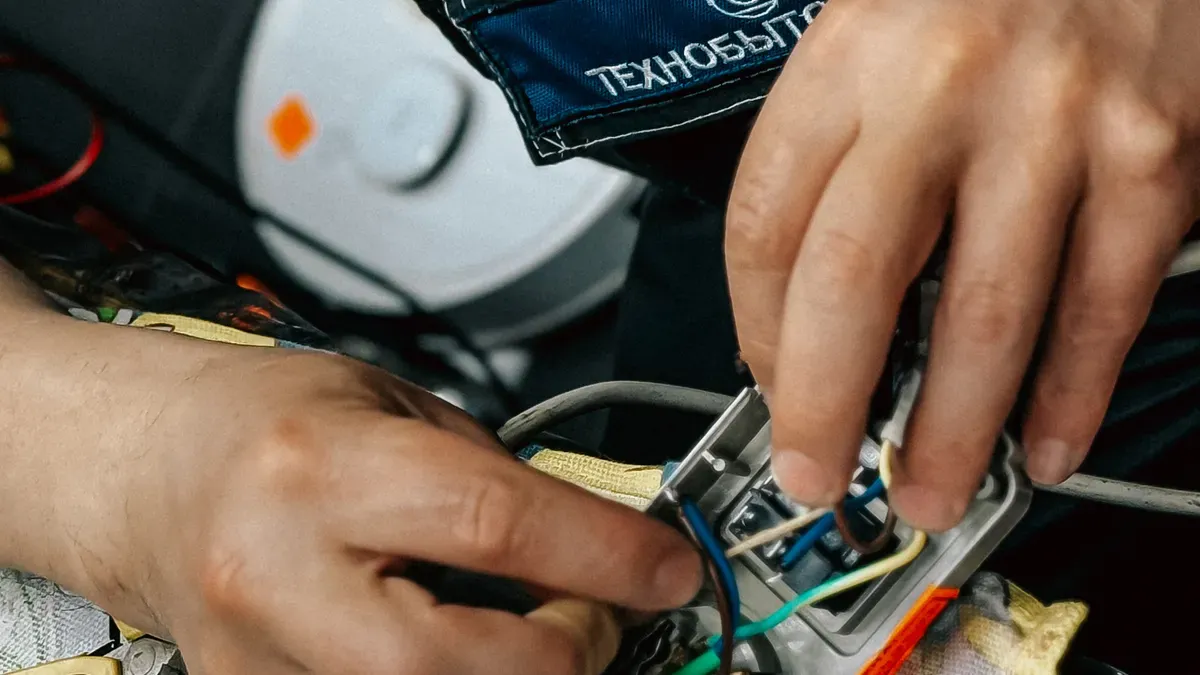
Every pin in your connector has a job. Mixing power and signal wires in the same layout causes trouble. Power wires carry high current that makes electromagnetic fields. Signal wires carry low-voltage data that those fields can ruin. Keeping them apart stops this interference before it begins.
Modern vehicles and industrial equipment need multi-branch harnesses with precise signal integrity that manual methods cannot reliably achieve. Automotive systems must handle multi-branch routing, power signal separation, EMI/EMC shielding, and strain points. Each wire connects a specific pin on one end to another pin. A single wrong wire stops the system from working correctly. Complex routing, manual design errors, and lack of traceability are top challenges that automated routing solves. These tools copy the physical layout and electrical performance under load, temperature changes, and vibration. They enforce power-signal separation in the routing algorithm.
Define the pinout clearly in your design papers. Write down connector part numbers like housing, contacts, seals, and clips. Note which pin connects to which. Include the finished length from connector face to connector face, wire gauge, insulation type, and color per circuit. A PDF drawing and a wire list cover most needed info. This detail stops assembly errors and makes sure every harness matches the wiring diagram.
Preventing Crosstalk in Compact Layouts
Space gets smaller, wires sit closer, and crosstalk increases. You need careful methods to keep signal quality in a compact custom wire harness. Manage cable pair handling, stripping, and untwisting length during setup. Keep untwisting length short and steady to preserve pair shape. Bad shape affects impedance, skew, and crosstalk performance. Use 360-degree shield crimping or soldering when told. Avoid long pigtail ground connections because they lower shielding effectiveness.
Separate power bundles from sensitive signal bundles when routing. Follow bend radius and strain relief rules. Shielded cable assemblies have conductive shield around inner wires to block outside interference. The main benefit for compact harness design is less crosstalk between nearby wires and better EMI protection.
After assembly, each harness gets electrical testing. Inspectors check connector integrity: all terminals are fully in place, retaining latches are locked, and polarizing keys point the right way. A continuity tester checks every connection against the wiring diagram. It finds wrong wires and partial breaks. For high-current harnesses, a micro-ohmmeter test makes sure resistance stays within limits. Only harnesses that pass are approved.
4. Cable Flexibility and Durability
Bend Radius and Dynamic Flex Life
Bend radius is the smallest curve a cable can make without getting damaged. If you bend it tighter, the conductor gets crushed or the insulation cracks. Cables used in moving parts need to handle bending again and again. You have to match the bend radius spec to the path where you install it.
The conductor class decides how long a cable lasts when it keeps flexing. Each class covers a certain number of cycles. The table below shows the usual flex ratings.
A common 6-axis industrial robot runs 10 cycles per minute for 16 hours a day. That adds up to about 2.8 million flex cycles each year. Over a 5-year service life, that equals 14 million cycles. Engineering teams aim for cables rated at 1.5 to 2 times the calculated lifetime. So 20 to 30 million cycles is a normal spec for robots that run all the time.
UV and Ozone Resistance for Outdoor Use
Outdoor exposure harms cable jackets in a specific way. UV radiation breaks the polymer chains on the jacket surface. This creates free radicals. Then ozone attacks these weak spots. Cracks form much faster than from either stressor by itself. When UV and ozone combine, jackets break down quicker.
You need a jacket material that can handle this attack. The table below compares common materials.
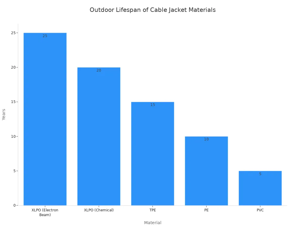
Electron-beam cross-linked XLPO gives the best outdoor lifespan. The electron-beam process creates a denser, more even cross-linked network. This leads to better hot-set performance and more consistent batch quality. It also resists combined UV and ozone attack better. This material has UV stabilizers and antiozonants to fight the combined degradation mechanism.
For a Custom Wire Harness used outdoors, pick XLPO or TPE for the jacket. These materials stay flexible and keep their seal over many years of sun and ozone exposure.
5. Connector Locking Mechanism
A connector that comes loose ruins every sealing feature you paid for. Water gets in the moment the plug slips out of the socket. Vibration, cable pull, and temperature changes all try to pull the two halves apart. Your locking mechanism is the feature that keeps the seal shut.
Threaded vs. Push-Pull Couplings
Threaded couplings screw the plug onto the receptacle. The threads give a mechanical advantage that presses the interface seal with steady force. This design works well in high-vibration places because the threads resist backing out. A bayonet version locks with a quarter turn and a detent, which speeds up field service while still holding under stress.
Push-pull couplings mate with a straight push and release with a pull on the outer sleeve. They save time during assembly and work well where technicians cannot turn their hands. The trade-off is less resistance to steady vibration. Choose push-pull for static indoor equipment. Choose threaded or bayonet for engine bays, chassis mounts, and outdoor cabinets.
Ensuring Positive Locking under Vibration
Vibration loosens connections and breaks the waterproof seal. Secure locking mechanisms keep the plug and socket tightly mated, so the seal stays compressed. Screw-lock and bayonet couplings hold connectors in place under mechanical stress and stop them from loosening over time. This keeps the waterproof seal intact for the whole service life of your Custom Wire Harness.
Locking mechanisms also resist cable movement and accidental disconnection. A secondary latch or a wire-to-connector lock adds a backup that stops partial unmating. Inspectors should check full engagement and the latch click during assembly. Add a pull test to your quality protocol to confirm the lock holds.
6. Shielding for EMI Protection
Braided vs. Foil Shielding Configurations
Electric motors, inverters, and radio transmitters send electromagnetic interference into your harness. That noise gets into your signal wires and messes up data. A shield around the wires blocks this attack. You pick between braided and foil shields based on frequency range and coverage needs.
Braided shields give you 70–95% coverage. They work best from DC to 15 MHz. Foil shields reach 100% coverage. They work well from 15 MHz into the GHz range. For low-voltage signal harnesses in cars, like CAN bus or LIN, pick a braided shield at 85% or higher coverage. High-voltage systems at 400V or 800V need a mix of foil and braid. This two-layer approach handles both low and high frequencies. A New energy wire harness in an electric car depends on this dual-layer plan to keep power and data clean.
Drain Wire Termination Techniques
A foil shield alone cannot carry noise to ground. You need a drain wire that runs the whole length of the cable. This bare wire touches the foil. It gives the interference an easy path to earth. For most signal uses, connect the drain wire at only one end. Grounding both ends creates a ground loop that adds noise instead of removing it.
For a Custom Wire Harness in a high-noise place, you may need to ground both ends. This choice depends on your grounding plan and the noise frequency. Keep the drain wire as short as possible at the connection point. A long pigtail reduces shielding effect. Crimp or solder the drain wire to the connector backshell with a strong bond. Test the shield-to-ground resistance after assembly to make sure the connection is good.
7. Precise Wire Gauge and Ampacity
Matching Gauge to Current Load
Wire gauge decides how much current your harness can handle without getting too hot. A wire that is too thin creates resistance, makes heat, and drops voltage along the way. A wire that is too thick adds weight, cost, and stiffness. You match the gauge to the real current load of each circuit.
Begin with the steady current for every circuit in your design. Then add a safety margin for inrush currents, which motors and capacitors pull at startup. A Custom Wire Harness for a motor drive may see short peaks that are many times higher than its running current. Size the conductor for those peaks, not just the average draw.
Use the ampacity tables from a named standard like IPC-2221 or the related UL wire standard. These tables list the top current for each AWG size at a given temperature rise. A New energy wire harness in a battery pack often carries hundreds of amps, so busbar or large-gauge cable takes the place of small hookup wire. An Industry equipment Wire Harness that powers a conveyor motor follows the same rule: gauge follows load.
Derating for High-Temperature Environments
Ampacity tables assume a certain surrounding temperature. Real installations hardly ever match that assumption. When the surrounding temperature goes up, the wire must carry less current to stay within its insulation temperature limit. This change is called derating.
The insulation rating sets your top limit. Standard PVC handles 70–80°C, XLPE sits at 90°C, and silicone reaches 180–200°C. Engine bay temperatures can go past 125°C. A PVC-insulated wire rated for a high current at room temperature cannot carry that same current inside an engine bay. You must derate it or switch to a higher-temperature insulation.
Bundle size matters too. Wires packed into a tight bundle cannot release heat as well as a single wire in open air. Apply a bundle derating factor on top of the ambient derating. For a Home Appliance Wire Harness inside a sealed control box, this step stops slow insulation breakdown. Every Wire Harness & Cable Assembly should record its derated ampacity so the installer knows the real limit.
8. Effective Strain Relief
Overmolding vs. Heat Shrink Boots
Strain relief keeps mechanical stress from reaching your terminations. Without it, cables move freely and pull right on connector pins. Sharp edges cut through jackets. Pulling forces harm conductors inside. Industry data shows that about 40–60% of connector failures begin with poor strain relief design.
Overmolding and heat shrink boots fix this problem at very different strength levels. Overmolding wraps the connector backshell and wire exit in one molded piece. This bond spreads mechanical loads across a larger cable section. Heat shrink boots reinforce the termination through jacket-to-boot friction alone.
Heat shrink gives limited strain relief. It is not made for heavy pulling, constant vibration, or repeated flexing. Pick overmolding for any Custom Wire Harness that faces dynamic motion or high pull forces.
Vibration Resistance at Backshell
Constant vibration causes fretting corrosion at contacts. It wears down insulation against mounting surfaces. It also weakens conductors at stress concentration points. These problems hit automotive, aerospace, and heavy equipment applications hardest. An Industry equipment Wire Harness on a vibrating press or conveyor needs backshell protection built for that load.
Backshells give strain relief and cable support in mission-critical applications. Cable clamps stop wires from ripping out of the connector. Shape memory metal rings, such as Tinel-Lock, shrink evenly around the cable braid after heating. This makes a 360° circular connection with natural resistance to severe shock and vibration. Tinel-Lock backshells handle temperature cycling from -65°C to 200°C while keeping electrical continuity. They come in TXR Series screened backshells for MIL-DTL 5015, MIL-DTL-26482, and MIL-DTL-38999 connectors.
Add heat-shrink boots with adhesive to a Tinel-Lock assembly for an environmental seal. This combination boosts strain relief between the backshell and cable jacket. It lowers stress on wiring across the full service life.
9. Quality Assurance Testing
Continuity and Hi-Pot Testing Protocols
Every Wire Harness & Cable Assembly has to pass electrical tests before it leaves the factory. Continuity testing checks each connection against your wiring diagram. A tester sends a small signal through every circuit. It catches wrong wires, open circuits, and partial breaks. For high-current harnesses, a micro-ohmmeter test makes sure resistance stays within limits. Only harnesses that pass move on to the next stage.
Hi-Pot testing sends a high voltage through the insulation to prove it can handle stress. UL 758 sets the standard for wires and wire harnesses. The table below shows typical test parameters.
Test Voltage = (Rated Voltage × 2) + 1000 V
The actual test voltage shall be adjusted according to the product type and the applicable standard. Test durations typically range from 1 to 60 seconds, with the objective of confirming insulation stability over a defined period. Pass criteria generally require no dielectric breakdown and no flashover during the test.
Immersion and Thermal Cycling Tests
Water ingress testing proves your sealing design works. You put the harness under water and check for leaks. This test proves the IP rating you picked is correct. A harness rated IP67 must survive 1 meter for 30 minutes. IP68 testing uses the depth and time your manufacturer sets. Any leak means the seal fails and the unit goes back for rework.
Thermal cycling copies years of temperature changes in a few weeks. Automotive under-hood environments demand a tough test profile.
Thermal cycling: typically -40°C to 125°C or 150°C, 1000 cycles minimum
Each cycle heats and cools the harness. This stress shows weak seals, cracked insulation, and loose terminations. A harness that passes both immersion and thermal cycling proves it can handle harsh outdoor or automotive conditions.
10. Compliance with Industry Standards
UL and VDE Certification for Safety
Certification proves your harness meets safety rules that are recognized. UL and VDE test different things, so you pick based on your market. UL checks flame spread (FT1/FT2), voltage withstand, and mechanical wear. It fits portable cords, extension leads, and products sold in North America. VDE checks fire behavior, insulation sticking at high heat, and aging under load. It gives strong proof for fixed setups and repeated flex cycles like robot arms. VDE works well for CE-marked products and industrial gear that needs EU alignment.
Physical specs can be the same between VDE and UL wires. Certification shows the test method, not better material. A Custom Wire Harness for the US needs UL 758 listing, which meets NEC rules. Canadian buyers want the cUL mark under CSA C22.2. European buyers want CE plus EN IEC 60335-1 for household gear. Your Home Appliance Wire Harness may need all three if you ship worldwide. Build the certification plan in the design phase, not after production starts.
RoHS and REACH Substance Restrictions
RoHS (2011/65/EU) bans harmful substances like lead, mercury, and cadmium in electronics. REACH covers chemical safety across the EU. These rules are not optional. One banned substance can stop your shipment at the border. Ask your supplier for material info for every conductor, jacket, and connector part.
Compliance also covers your factory process. ISO 9001 shows steady quality in manufacturing. IPC/WHMA-A-620 sets work quality classes for assembly. A New energy wire harness or Industry equipment Wire Harness sold in Europe must carry RoHS documents. Every Wire Harness & Cable Assembly should ship with a statement that it follows the rules. Keep these records current because regulators update substance lists over time.
These ten features all work together as one system. If a seal is weak, a wire is too thin, or a shield is missing, the whole chain breaks. When you look at a Custom Wire Harness from a maker like Xiamen Kehan Electronics Co., Ltd., check every item on this list. If you skip strain relief or shielding, your total cost of ownership goes up because of field returns and downtime. Compare what your supplier offers against these points today. Ask for a design consultation for a 2026-ready Custom Wire Harness that can handle harsh environments.
FAQ
What makes a Custom Wire Harness suitable for harsh outdoor environments?
You need the right jacket material, good sealing, and UV resistance. Materials like XLPO or TPE stand up well to sunlight and ozone. Use these with IP67 or IP68 connectors. This mix keeps your Custom Wire Harness safe from moisture, chemicals, and temperature changes.
How do I choose between IP67 and IP68 for my application?
IP67 handles short-term soaking up to 1 meter for 30 minutes. IP68 goes deeper and longer, but the maker sets those limits. Pick IP68 for washdown areas or possible flooding. Pick IP67 for closed spaces with occasional moisture.
Why does pin configuration matter in a compact connector?
Power and signal wires must stay apart. High-current power lines make electromagnetic fields. These fields mess up low-voltage signals. A well-planned pinout stops crosstalk and keeps data clean. Your Wire Harness & Cable Assembly relies on this separation for steady performance.
What testing proves my harness can handle thermal stress?
Thermal cycling tests copy years of temperature changes in weeks. A typical automotive profile runs from -40°C to 125°C or 150°C for 1000 cycles minimum. This test shows weak seals, cracked insulation, and loose terminations. Your New energy wire harness should pass this before shipping.
Do I need UL and VDE certification for my wire harness?
It depends on your market. UL 758 listing meets North American rules. VDE works for CE-marked products in Europe. A Home Appliance Wire Harness sold worldwide may need both. An Industry equipment Wire Harness for EU buyers needs RoHS documents too. Plan certification early in design.