


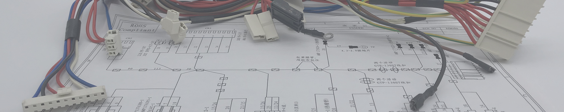
Custom Outdoor Charging Equipment Wire Harnesses: Built for Rain, Salt, Cold, and 350 A of Heat
2026-09-18 14:15Custom Outdoor Charging Equipment Wire Harnesses: Built for Rain, Salt, Cold, and 350 A of Heat
A marina operator in Norway sent us a box last February. Fourteen J1772 handles from outdoor AC pedestals along the docks, all of them from the same supplier, all of them one winter old. Every single one had a crack in the jacket right where the cable exits the handle body. Not a scratch — a crack, split through to the shield, with green copper visible inside. Two of the pedestals had tripped their RCD and nobody could figure out why until we cut the handle open and found standing water in the strain-relief boot.
The cable was rated for the job on paper. Outdoor, flexible, -40 °C to +90 °C printed right on the jacket. What it was not rated for was being flexed at -18 °C, twelve times a day, by people wearing gloves, while salt spray dried on the surface and the sun hit it for four months of the year. That is the gap between a datasheet and an outdoor charging installation, and closing that gap is most of what this article is about.
What this article covers:
What actually counts as an "outdoor charging equipment" harness, and why the category is wider than EV chargers
The seven environmental stressors that kill outdoor harnesses, and what we do about each one
The four circuit families inside every charging unit, and how they differ
Sizing the DC power path for real heat, not datasheet heat
Connector and sealing choices: IP67 vs IP68 vs IP69K, and where each one is honest
Control pilot, proximity pilot, PLC, RS-485, CAN — what each line has to survive
Grounding, surge, and the leakage-current loop nobody wants to own
Jacket chemistry: UV, cold flex, hydrolysis, and why "outdoor rated" is not enough
Cable management, strain relief, and retractors
How we build and test an outdoor charging harness
The failures we get paid to fix from other suppliers
A spec template you can copy into your next RFQ
Table of Contents
What "outdoor charging equipment" really covers
When people hear "outdoor charging," they think of an EV charger on a pole. That is one product family. It is not the whole category, and if you are sourcing a harness it matters that you know which family you are in, because the requirements are different.
The units that land on our bench most often:
AC charging pedestals and wallboxes. 7 kW single-phase up to 22 kW three-phase. Type 2 or J1772 connector, sometimes a tethered cable, sometimes a socket. The harness inside is modest — power in, contactor, meter, control board, connector out — but the entire unit is outdoors and the cable is handled by humans every day.
DC fast charger cabinets. 30 kW to 350 kW and up. Separate power cabinet and dispenser, connected by a long DC cable run, sometimes liquid-cooled. This is where the harness work gets serious: 200 A to 500 A continuous, high voltage, and a control layer that has to talk OCPP to the cloud.
Portable and semi-portable outdoor chargers. The ones that live in a trunk or a shed, get rained on, get dropped, and get plugged into whatever socket is available. NEMA 14-50, Schuko, CEE, industrial pin-and-sleeve.
E-bike, e-scooter, and light EV charging posts. Lower power, much higher unit volume, much harsher handling. Also much more price-sensitive, which is exactly why so many of these leak.
Battery cabinets and energy storage charging interfaces. Outdoor BESS cabinets, telecom backup, off-grid solar charging. High current DC, sealed connectors, wide temperature.
Industrial and fleet depot charging. Depot chargers, pantograph systems, opportunity charging for buses and forklifts. Often three-shift duty, high dust, and a maintenance team that will absolutely tell you which part failed.
Marine and RV shore power charging. 16 A to 63 A, salt air, constant motion, and a user base that will unplug a live connector because the socket is behind a locker.
Different families, same core problem. You are putting electrical hardware outside, permanently, in a place where nobody is watching it, and expecting it to survive a decade of weather and a few thousand people pulling on the cable.
Why outdoor is a different design problem
We have built a lot of indoor appliance and industrial harnesses. Outdoor charging is harder, and not for the reason people usually give.
The reason people give is water. Water is a real problem, but water gets designed for almost by reflex — you pick a sealed connector, you add a gasket, you pot the back of the housing. What actually kills outdoor harnesses is the combination, and it is always a combination. Water plus cold. UV plus flex. Salt plus heat. Each one alone is manageable; two of them together attack the same material from different directions.
| Stressor | What it does to the harness | Field symptom | What we do about it |
|---|---|---|---|
| Liquid water / rain / pooling | Wicks through strain relief, sits in boots, corrodes crimps | RCD tripping, intermittent continuity, green copper | Sealed connectors, gel-filled crimp, drain path designed in, cable exits pointing down |
| UV (1000+ kWh/m² per year) | Photo-oxidation of jacket surface, chalky then cracked | Jacket looks faded, then splits lengthwise | Black XLPO or TPE-V jacket with carbon black loading; never PVC on a sun-exposed run |
| Cold flex (-20 °C and below) | Jacket and insulation go glassy, crack on repeated bending | Cracks at the strain relief and at the connector nose | -40 °C cold-flex rated compounds, verified by cold bend test at -30 °C, not by datasheet |
| Salt spray / coastal chloride | Pitting on exposed copper, corrosion creep into crimped joints | Resistance rise over 18 months, hot spots at terminations | Tin or silver plating, closed-barrel crimps, 720 h salt spray on the assembled unit |
| Thermal cycling (sun load + current load) | Differential expansion between copper, insulation, and jacket; gasket compression set | Seal weeps after two summers; terminal torque relaxes | Material pairs matched on CTE, silicone gaskets, thermal cycling with current applied |
| Mechanical abuse | Drive-over, dropped connector, cable yanked out of the holder, door slammed on it | Conductor broken inside intact jacket (the worst kind of failure) | Stranded conductor class 5/6, added strain relief, bend radius enforced at both ends |
| Dust, sand, agricultural chemistry | Abrasion of jacket, blocked drainage, gasket damage | Chafed runs, water ingress in a housing that passed IP test new | IP6X gasket design with a defined drainage path; abrasion-resistant jacket option |
Notice that the last two columns are where the money goes. Anyone can specify a "UV-resistant outdoor cable." The work is in the test plan that proves the assembly still holds up after the combination, and in the mechanical details — where the cable exits, how the boot is shaped, whether there is a place for water to leave instead of a place for it to sit.
The four circuit families inside a charging unit
Every charging unit we build for, from a 7 kW wallbox to a 350 kW dispenser, breaks down into the same four families of wiring. We sort the drawing this way before we quote, because the four families have almost nothing in common on the build floor.
| Family | Typical circuits | Current / voltage | Wire and termination approach | Where it fails outdoors |
|---|---|---|---|---|
| Power input (AC) | L1/L2/L3, N, PE from the supply, input contactor, surge device, AC filter | 16–63 A per phase, 230/400 V AC | Fine-strand copper, ring or tubular lug, torque-controlled, phase-colored | Loose terminations from thermal cycling; lugs that were crimped with the wrong die |
| DC power path | Rectifier output to DC bus, DC bus to dispenser, output to connector, output contactors | 60–500 A, 200–1000 V DC | Large-section copper or aluminum, shielded where required, liquid cooling on the highest currents | Hot spots at crimps, insulation damage during routing, inadequate bend radius |
| Control and safety | Control pilot (CP), proximity pilot (PP), RCD/GFCI trip coil, leakage sensor, contactor coils, door and E-stop interlocks | 12 V to 24 V control, 1 kHz PWM on CP | Small-gauge multi-core, twisted where differential, separate from power runs | Induced noise on CP from adjacent power wiring; water ingress into the CP pin at the connector |
| Communication and sensing | OCPP backhaul (Ethernet, 4G, Wi-Fi), RS-485 to the energy meter, RFID reader, internal CAN to the BMS or power modules, NTC temperature sensors | Data rates to 1 Gbit/s; sensor signals 0–10 V or NTC | Impedance-controlled pairs for Ethernet, twisted shielded pair for RS-485, separate analog returns | Shield terminated at both ends; Ethernet pair untwisted at the splice; sensor ground loops |
If your supplier quotes a charging harness as one lump, without telling you which family is driving the cost, they are guessing. The DC power path is where the material cost lives. The control family is where the warranty claims live. Both have to be designed by someone who has actually built one.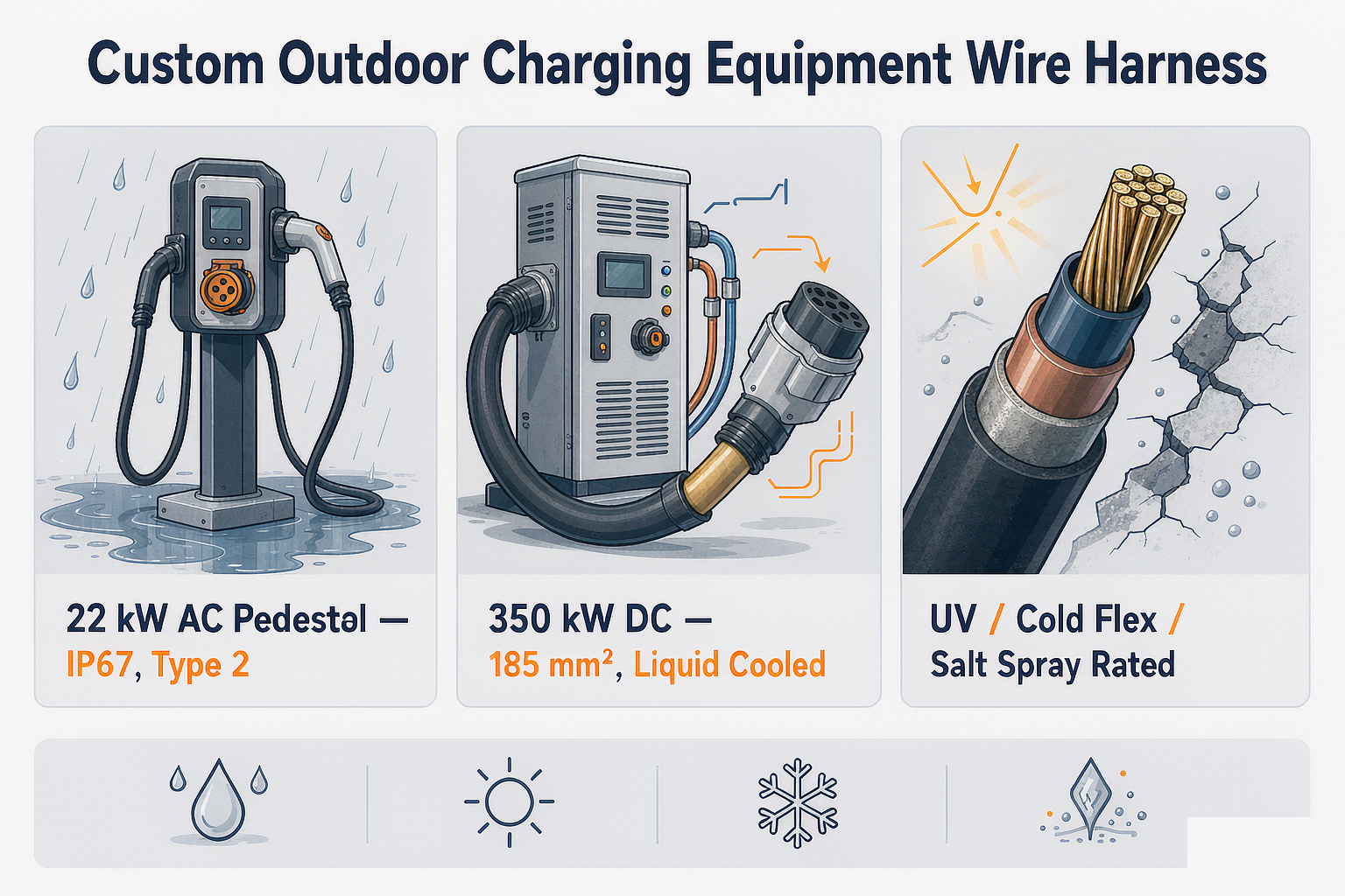
The DC power path: sizing for real heat
Here is the part that gets under-specified in most RFQs: "4 AWG, 350 A" or some other combination that cannot work.
Conductor sizing has two constraints and people usually only check one. Voltage drop is the one everyone checks, and on a 400 V or 800 V DC bus it is almost never the problem — you have hundreds of volts of headroom. Ampacity is the one people skip, and it is the one that sets your enclosure on fire, or more commonly, quietly cooks a crimp for two years until it oxidizes into a resistive joint.
| Continuous current | Typical internal conductor (105 °C rated, single, free air) | Voltage drop over a 5 m cable (10 m round trip) | Where you see it | Note |
|---|---|---|---|---|
| 32 A | 6 mm² (approx. 9 AWG) | ≈ 1.0 V | 22 kW three-phase AC output | VD is visible here; at 230 V single-phase it is 0.4 %, still acceptable but worth watching |
| 60 A | 16 mm² (approx. 5 AWG) | ≈ 0.7 V | 30–50 kW DC module output | The bottom of the DC range. Air-cooled cable is still fine |
| 80 A | 25 mm² (approx. 3 AWG) | ≈ 0.6 V | 60 kW DC | This is where cable weight starts to matter for a tethered cable the user lifts |
| 125 A | 35 mm² (approx. 2 AWG) | ≈ 0.7 V | 100–120 kW DC | Termination quality becomes the limiting factor, not the copper |
| 150 A | 50 mm² (approx. 1/0 AWG) | ≈ 0.6 V | 150 kW DC | Above this, liquid cooling starts to win on cable diameter and handling weight |
| 250 A | 95 mm² (approx. 3/0 AWG) air-cooled, or 35–50 mm² liquid-cooled | ≈ 0.5 V | 250 kW DC | Air-cooled cable at this current is heavy and stiff in cold weather — a real usability problem |
| 350 A + | 185 mm² (approx. 350 kcmil) air-cooled, or 35–50 mm² liquid-cooled | ≈ 0.4 V | 350–500 kW DC megawatt-adjacent systems | Coolant path, fittings, and leak integrity become part of the harness scope |
Read the table as a starting point, not a spec. The figures assume copper at 20 °C, one cable, not bundled, in free air at 30 °C ambient. Put three cables in a sealed enclosure with no airflow and every one of those currents comes down. Derate — typically 0.7 to 0.8 for bundled runs in a closed cabinet — and then thermal-test the real assembly with the real current for the real duty cycle. ABB and Phoenix Contact publish good derating curves; use them, then verify.
Two things we do that a lot of suppliers do not:
We thermally test the finished assembly, not the cable. A 95 mm² cable is fine. A 95 mm² cable crimped into a lug that sits against a plastic terminal block, inside a sealed cabinet, at 45 °C ambient, is a different question. We run the assembly at rated current with thermocouples on every termination for several hours until the temperatures stabilize, and we report the delta above ambient.
We measure the crimp, not just the pull force. Pull force tells you the crimp will not come off. It does not tell you the crimp resistance. We do micro-ohm measurement on high-current terminations and flag anything outside our window before it ships.
Connectors and sealing: IP67 vs IP68 vs IP69K
IP ratings are the most abused three characters in the industry. A connector that is IP67 when mated and untouched is not IP67 after two years of thermal cycling, and it is definitely not IP67 in the orientation your installer mounted it in.
The honest version: IP44 keeps rain out of a housing that is already fairly protected. IP54 handles splashing. IP66 handles a directed water jet, which is what a pressure washer or a heavy storm does. IP67 handles 30 minutes immersed at 1 m, static. IP68 is whatever the manufacturer negotiated with the test house — it is immersion at a depth the manufacturer chooses and states. IP69K is high-pressure, high-temperature jet cleaning, 80 °C water at 80 to 100 bar, and it is mostly relevant for food processing, vehicles that get washed down, and agricultural equipment.
| Connector family | Typical use in outdoor charging | Rating achieved in practice | What to watch |
|---|---|---|---|
| IEC 62196 Type 2 (Mennekes) | AC 3-phase output, 22 kW; socket or tethered | IP44 to IP67 depending on the mating half and the boot | Water collects in the socket face if it faces up. The locking actuator is a common wear item. Pin temperature sensing is often the difference between a safe unit and a recall. |
| CCS2 / CCS1 (Combo) | DC fast charging output, 150–350 kW | IP54 to IP67 at the connector, IP6K9K on higher-end units | The DC pins carry the current and the heat. Cable-to-handle transition is the number one water ingress point we see in tear-downs. |
| NACS / SAE J3400 | North American AC and DC through one connector | IP67 typical for premium assemblies | Compact body means less room for a seal and a strain relief. Small latches wear faster. Verify the latch life against your handle cycles. |
| Anderson SB / Powerpole | DC output on chargers and battery cabinets, 50–350 A | IP20 to IP68 depending on the hood used | The bare connector is not weatherproof. It needs a hood or it needs to live inside a housing. Color coding prevents some very expensive mistakes. |
| Heavy-duty DC lugs and busbar interfaces (M8/M10 stud) | Internal cabinet connections, 100–500 A | Not applicable — this is an internal termination | Insulation boots, creepage/clearance distance, and torque marking. We torque-stripe every high-current stud so incoming inspection can verify without loosening anything. |
| M12 / M8 circular, metal shell | Sensors, CP/PP breakouts, cabinet-to-door harnesses | IP67 to IP69K | Over-torquing the coupling nut cracks the insert. Use a torque wrench, not a strong wrist. |
| Industrial Ethernet (M12 X-coded, ix Industrial, RJ45 in a sealed shell) | OCPP backhaul, internal controller links | IP67 with the correct shell | A standard RJ45 in a plain bulkhead is an IP20 part. It is not "outdoor Ethernet" because the cabinet is outside. |
| Liquid-cooled DC connector assemblies | 350 kW and above | IP67 assembly level, with a separate leak requirement | Coolant fittings, hose routing, and a leak test on every unit. This is a plumbing job as much as an electrical one. |
One practical rule we apply on every outdoor build: the cable must exit the housing pointing down, or it must have a defined drainage path, or it must be sealed. Pick one. A cable exiting horizontally into a boot that fills with water is the single most common root cause in the returns we see, and it is a two-dollar fix at the design stage.
Control and communication wiring
The power path gets all the attention. The control wiring causes all the mystery faults. This is the layer where a unit that works perfectly on the bench in July starts misbehaving in a parking lot in January.
| Line | What it carries | Electrical character | Harness requirement | Outdoor-specific failure |
|---|---|---|---|---|
| Control Pilot (CP) | PWM signal telling the vehicle how much current is available | ±12 V square wave, 1 kHz, single-ended | Twisted with PE, routed away from DC and AC power conductors | Capacitance change from water ingress in the connector body shifts the PWM edges; the vehicle reads a different current than the charger intended |
| Proximity Pilot (PP) | Cable ampacity coding, latch detection | Resistance-coded, low current | Clean, stable resistance path; no shared return with high-current circuits | Moisture across the PP contact creates a false ampacity reading — the charger throttles for no reason |
| Power Line Communication (PLC / ISO 15118) | Plug & Charge, V2G, certificate exchange | High-frequency carrier superimposed on CP | Controlled impedance on the CP pair, defined attenuation, filter placement per the reference design | Marginal attenuation that passes at 20 °C fails at -20 °C. Test PLC performance across the temperature range, not just at room temperature |
| RS-485 (meter, energy management, RFID) | Modbus and proprietary protocols | Differential, 9600 to 115 kbit/s | Twisted shielded pair; drain terminated at one end only unless the design requires otherwise | Drain grounded at both ends — hum, communication dropouts, and a fault that "fixes itself" when the two units are on different supplies |
| CAN / CAN-FD | Internal bus to power modules, BMS in battery cabinets | Differential, 250 kbit/s to 5 Mbit/s | 120 Ω termination, stub length controlled, twisted pair with 33 turns/m minimum | Long stubs added during field service. At 500 kbit/s a 1.5 m stub is already marginal |
| Ethernet 100BASE-T1 / 1000BASE-T1 | Controller to cloud gateway, internal board-to-board | Single or dual pair, impedance-controlled | Pair geometry maintained through the splice and the connector; TDR verification on the finished assembly | An untwisted 20 mm section at a splice. It passes continuity, it passes a quick ping, and it fails intermittently at temperature |
| NTC temperature sensors (connector, cable, cabinet) | Over-temperature protection, current derating | Resistance, mV-level signal | Dedicated return; do not share the ground with the contactor coil | Shared ground with a switching load makes the temperature reading jump whenever the contactor pulls in |
| RCD / GFCI sense and trip | Residual current detection and disconnection | Low-level differential signal, trip coil drive | Short, symmetric, shielded where the design calls for it; sense pair routed together | Asymmetric routing and moisture-induced leakage cause spurious trips, which is the top complaint on outdoor AC installations |
The design intent here is simple to state and harder to execute: keep the small signals away from the big ones, keep the returns separate, and keep the pair geometry intact from end to end. Every intermittent charging fault we have torn down in the last three years came from one of those three, plus water.
Grounding, surge, and the leakage-current loop
Grounding on an outdoor charger has to do two jobs that pull in opposite directions.
Job one is safety. The protective earth has to carry fault current long enough to trip the breaker. That means a low-impedance path with solid terminations, which means the PE conductor is a power conductor, not a signal conductor. If your PE is landed with the same size wire and the same lug as a signal return, it was not designed by someone who thought about fault current.
Job two is reference. The control and communication circuits need a stable reference, and the sensor returns need to be quiet. If you bond everything to one big ground bar with no thought, the switching currents from the contactors and the DC-DC converters ride on the same reference as your NTC measurements and your CP signal.
What we do about it, in practice:
Separate PE from signal return. Two different nets, landed on two different points, joined only where the customer's schematic says to join them — which is usually at a single star point.
Heavy-gauge PE with an insulated boot. Sized to the phase conductor per the local code (IEC 60364 or NEC 250, depending on market), with a boot over the terminal so a service technician's tool cannot bridge it to an adjacent live lug.
Every high-current stud torque-striped. A diagonal paint line across the nut and the lug. Incoming inspection can verify the torque without a wrench. Also makes it obvious if anything has moved after a thermal cycle.
Surge path short and direct. The cable from the surge protective device to the PE bar should be as short and as straight as you can physically make it. An extra 300 mm of loop inductance is the difference between a surge device that clamps and one that lets the transient through.
Chassis bonding verified by test, not by drawing. We measure the resistance from every conductive enclosure panel back to the PE entry point. If it is above our limit, we fix it before the hipot even runs.
The spurious-trip problem deserves a separate sentence, because it costs installers real money. Nuisance RCD trips on outdoor AC chargers are almost always a cumulative-leakage issue: a little moisture in two connectors, a slightly damaged cable jacket, an EMI filter with a leakage current toward the top of its tolerance — none of them enough alone, all of them enough together on a rainy morning. We specify EMI filters with low leakage, we keep signal and PE routing symmetric, and we tell customers plainly when a 30 mA Type A device is going to be marginal and a Type B with a higher trip threshold is the honest answer.
Compliance by market
An outdoor charging harness is not a generic part. It is part of a product that has to be approved in the market it is sold into, and the harness carries a surprising share of that approval. The differences are worth knowing before you quote, because getting it wrong is a redesign, not a paperwork fix.
European Union. IEC 61851 for the conductive charging system, IEC 62196 for the connector, IEC 62955 for the residual DC current monitoring device, EN 61851-1 and -23 for the EMC and safety of the charging station. CE marking, EMC Directive 2014/30/EU, Low Voltage Directive 2014/35/EU, RoHS and REACH on every material in the BOM. The German VDE and the TÜV mark are not legally required but they open doors with utilities and fleet buyers.
United States. UL 2594 for the charging station, UL 2231 for the personnel protection system, UL 2251 for the connector, SAE J1772 for the AC connector and J3400 (NACS) for the combined connector. NEC Article 625 governs installation. The harness needs to be built with UL-recognized wire, connectors, and tubing if the end product is going to carry the mark — this is the single most common delay we see on US-bound programs.
Canada. CSA C22.2 and cUL equivalents. Usually the same build as the US version with different labels; sometimes not, and it is worth asking early.
United Kingdom. UKCA marking post-Brexit, plus the Electric Vehicles (Smart Charge Points) Regulations, which add a communication and cyber-security requirement that lands on your cloud link and therefore on your data wiring.
Japan. CHAdeMO for legacy DC charging, plus PSE under the DENAN law. Different connector, different harness, different test plan.
China. GB/T 20234 for connectors — separate AC and DC connectors, 250 A class DC, 1000 V.
Australia and New Zealand. AS/NZS 3000 and the relevant IEC derivatives, plus state-level metering rules if the unit is used for billing.
Marine and offshore. Beyond shore power standards, expect ignition-protection or specific marine-grade requirements on the enclosure and the bonding, and expect salt fog testing at a duration nobody quotes for on land.
We are not a certification body and we do not pretend to be. What we do is build the harness to the compliant material set, keep the documentation traceable, and hand your test lab a build that will not be the reason you fail. If you tell us the target market and the mark you are going for, we will tell you in the DFM where we think the risk is.
Jacket chemistry: UV, cold flex, hydrolysis
The jacket is the cheapest part of the harness and the one that decides whether you have a warranty problem.
Four things kill an outdoor jacket, in rough order of how often we see them:
UV degradation. Sunlight breaks the polymer chains at the surface. The jacket first goes chalky, then the surface cracks, then the cracks go through and expose the shield or the individual conductors. PVC is the worst offender and also the cheapest, which is why it shows up on so many budget outdoor products. We default to black cross-linked polyolefin (XLPO) or a TPE-V compound with a carbon black loading for any run that sees sun, and we do not accept "outdoor grade PVC" as a specification.
Cold flex cracking. This is the Norway failure at the top of this article. A jacket that is flexible at 20 °C can be brittle at -20 °C, and the crack always starts where the cable is forced to bend — the exit from the handle, the strain relief boot, the door hinge. We test cold bend at -30 °C on the assembled cable, not just the raw jacket, because the assembly is where the bend radius is wrong.
Hydrolysis and plasticizer migration. Some TPE and PUR compounds absorb moisture over time and lose mechanical strength, especially in warm humid climates. Others slowly lose plasticizer, go hard, and crack. This is a chemistry question, and it is why we ask the customer for the actual deployment climate rather than accepting "outdoor."
Abrasion and mechanical damage. Dragging a cable across a concrete forecourt, a fork of a pallet truck, or the edge of a metal pedestal. A tougher jacket is part of the answer, but a properly designed strain relief and a cable that is not under tension is most of it.
One more thing about jackets, which is not a spectrum. It is thermal conductivity. A thicker, tougher jacket holds more heat in the copper. If you are already tight on ampacity, adding a heavy-duty outer jacket makes the thermal problem worse. This is exactly why we test thermally at the assembly level — you cannot pick a jacket by looking at a material datasheet alone.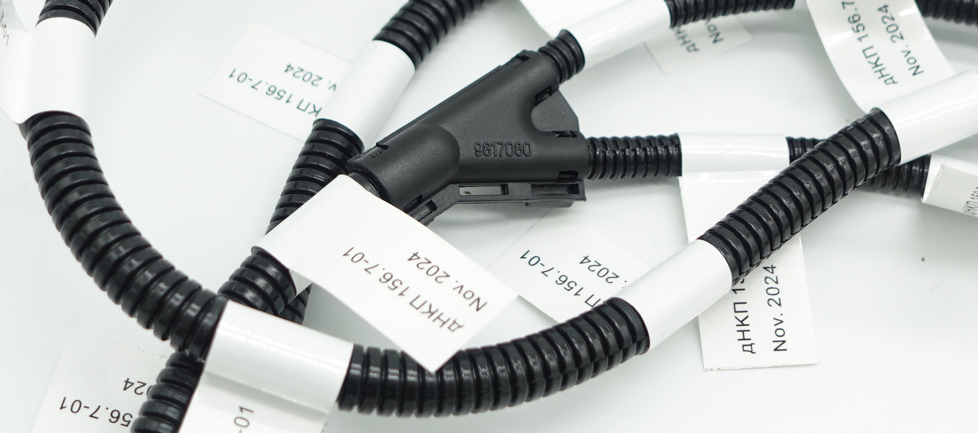
Cable management, strain relief, and retractors
Mechanical details are where a well-specified harness stops being well-specified. We care about them because they are the failures that come back.
The bend radius is a real number. Typically 6× to 8× the cable outer diameter for a flexible charging cable, more for a stiff one, and it applies at both ends. Cable assemblies are destroyed by violations at the exit, not in the middle.
Exit direction is a design decision, not an installation detail. Down and away from the housing. Anything else needs a drainage path designed in, because gravity is not going to negotiate.
Strain relief has to survive the pull. We test the strain relief per the applicable standard (typically 200 N for a handheld application, higher for a wall-mounted tethered unit) and we pull on the jacket, not on the individual conductors. If your supplier's strain relief is a zip tie, this is the test that finds it.
Retractors and cable management systems. Retractors solve the trip hazard and the driveway-abuse problem, and they introduce a new one: the cable now lives under constant low tension and is flexed through a fixed small-diameter arc thousands of times. Retractor-associated harnesses need a high-flex conductor design and a longer, more careful strain relief. Test the flex life, do not estimate it.
Handle and holster interfaces. The connector holster is a wear surface. The cable sleeve chafes where the handle enters the holster, ten times a day. A sacrificial abrasion sleeve at that point costs almost nothing and takes a common wear point out of the warranty window.
Field service access. Leave enough service loop inside the cabinet that a technician can pull the control board out without disconnecting the DC bus. We add this at the design stage as standard; a lot of our competitors do not, and you find out at the first warranty repair.
How we build and test an outdoor charging harness
The build process for a charging harness is not exotic. The discipline is in the sequence and in the tests that are not optional.
DFM review against the customer's drawing and the target market. We look for ampacity that does not close, jacket chemistry that will not survive the deployment climate, sealing that stops being sealing once you account for the mounting orientation, and control wiring routed too close to the power path. Two working days, no charge.
Materials locked and traceable. Wire lot, connector batch, gasket date code, plating spec. Every lot is logged against the program. When you call us in two years and ask about a specific serial number, we can tell you what was in it.
Cut, strip, and crimp with calibrated tooling. Production of crimp heights per lot, tooling calibration on a schedule, and closed-barrel crimps on every high-current termination.
In-process pull-force on every crimp on high-current and control terminations. Not a sample. Every one. It costs 30 seconds per terminal and it catches the one bad crimp that would have become a field failure.
Assembly with sealing verified as you go. Gaskets seated, boots correctly oriented, cables exiting in the designed direction, no seal pushed out of position by an over-torqued connector.
100 % electrical test. Continuity, polarity, and hipot on every assembly. Insulation resistance on the power path. Micro-ohm on high-current terminations. TDR on Ethernet pairs.
Environmental and mechanical validation for the program. Salt spray, thermal cycling with current applied, cold bend, IP test in the mounted orientation, strain relief pull, flex life if the cable is handled or retracted.
Document pack and traceability with the shipment. Test records, material certs, and the serial number map. Your incoming inspection gets a document set, not an apology.
| Test | What it catches | Applied to | Frequency | Acceptance |
|---|---|---|---|---|
| Continuity and polarity | Wrong pin, missing wire, swapped pair | Every assembly | 100 % | Per customer drawing |
| Hipot / dielectric withstand | Insulation defects, creepage problems, contamination | Power and control conductors vs PE | 100 % | Per applicable standard, typically 1500–2500 V AC for 1 s or the program-specific value |
| Insulation resistance | Moisture ingress, marginal insulation, contamination | DC power path and control circuits | 100 % on power path | Program-specific; typically ≥ 20 MΩ at 500 V DC |
| Micro-ohm on terminations | Cold crimps, oxidized joints, bad plating | High-current terminations | 100 % on DC path | Within window derived from conductor, lug, and length |
| Pull force on crimps | Under-crimped or wrong-die terminations | High-current and control terminals | 100 % on high-current, 100 % on control | Per terminal and wire combination, per the relevant standard |
| Chassis and shield bonding resistance | High-impedance PE path, bad shield termination | Enclosure panels, shields, PE entry | 100 % | Below program limit, measured not assumed |
| Strain relief pull | Weak cable retention, zip-tie style relief | All external cables | Per batch, plus on every design change | 200 N typical for handheld, per program for wall units |
| IP test in mounted orientation | Water ingress at the connector, boot, and cable exit | Assembled unit or representative assembly | Design verification, plus after any mechanical change | Rated IP level, tested in the orientation the customer installs it in |
| Salt spray | Corrosion of terminations and plating | Assembled harness, coastal programs | Design verification | Typically 720 h neutral salt spray without functional degradation |
| Thermal cycling with current applied | Relaxation of terminations, seal compression set, ampacity mistakes | Power path assembly | Design verification | No termination above the program temperature limit; no resistance drift beyond the window |
| Cold bend at -30 °C | Jacket and insulation cracking in winter service | External flexible cable assembly | Design verification, and on every jacket material change | No cracking, no visible damage; dielectric test passes after the bend |
| TDR on Ethernet and impedance-controlled pairs | Untwisted splice sections, impedance discontinuities | Data pairs | 100 % where specified | Impedance within the protocol window across the length |
| Leak integrity on liquid-cooled assemblies | Coolant leaks at fittings and hose interfaces | Liquid-cooled cable assemblies | 100 % | Pressure hold per the program spec, no loss |
The hipot and continuity testers are calibrated monthly. The thermal chambers and the salt spray cabinet have their own schedules. Every one of those tests generates a record that goes with the shipment, and the record has the operator's ID on it. This is not because our customers are difficult. It is because when something does go wrong, the difference between a one-week fix and a three-month argument is whether the data exists.
Failures we fix from other suppliers
These are patterns from harnesses that were returned, replaced, or pulled out of service in the last few years. We have made some of these mistakes ourselves in our early years, which is how we learned to look for them.
Cracked jacket at the strain relief, one winter old. The Norway marina case. Outdoor grade PVC, printed to -40 °C, brittle at -18 °C after UV exposure. Fixed with a -40 °C XLPO jacket and a longer, gentler strain relief geometry that spreads the bend over 60 mm instead of 15 mm.
Water standing in the handle boot. Cable exits the handle horizontally, boot has no drain, water pools at the crimp and the RCD trips a week later. Fixed by re-orienting the exit downward and adding a small drain slot at the low point of the boot.
"95 mm², 350 A" that was 70 mm². The conductor was printed 95 mm² but measured 70 mm² on a cross-section cut. At 350 A that is a 3× current density increase and the termination ran at 105 °C in a 30 °C cabinet. We measure the cross-section of every new wire lot and we do not accept the print legend as evidence.
Shield drain bonded at both ends on an RS-485 run. Communication dropouts on maybe 5 % of installations, always at sites where the charger and the energy meter were fed from different sub-panels. Fixed by terminating the drain at one end only.
CP pair routed alongside the DC bus for 400 mm. PLC (ISO 15118) would not establish on about a third of vehicles. The CP edges were distorted enough that the vehicle's interpretation of the available current was wrong. Fixed by re-routing and adding a proper separation from the power conductors.
Untwisted splice in a 100BASE-T1 pair. Passed continuity. Passed a bench ping for an hour. Failed intermittently once the cabinet got warm, because the impedance discontinuity became significant at temperature. Fixed by resplicing with the pair geometry held.
NTC return sharing a ground with the contactor coil. The cabinet temperature reading jumped 12 °C every time the contactor pulled in, which made the charger derate for no reason. Fixed with a dedicated sensor return. Cost of the fix: one wire.
Unbooted PE stud adjacent to a live DC stud. A service technician's tool bridged them during a routine inspection. Nobody was hurt. Fixed with insulated boots and a physical barrier between the PE and DC termination zones.
Gasket compressed beyond its recovery limit by an over-torqued housing screw. Passed IP67 when new, weeping at the first thermal cycle. Fixed with a torque spec, a marked fastener, and a molded compression stop in the housing.
Not one of those is exotic. Every one of them is a design or process decision made by someone who was moving fast. They are also all cheaper to prevent than to fix, which is the whole argument for paying attention to an outdoor harness at the drawing stage rather than at the first field failure.
RFQ spec template
If you are putting an outdoor charging harness out to quote, this is the data that lets us give you a real number instead of a placeholder with a 40 % contingency in it.
| Item | What to send | Why we need it |
|---|---|---|
| Unit type and rating | AC pedestal / wallbox / DC cabinet / portable / marine shore power, plus kW and voltage class | Sets the whole architecture: connector family, conductor sizing, cooling approach |
| Drawing or schematic | PDF or native CAD, all connectors labeled, all circuits identified | Source of truth for wire count, gauge, and routing |
| Connector BOM | Exact part numbers, manufacturer, mating half, sealing class, keying | Connector lead time is usually the long pole on a charging program. "Type 2 equivalent" is not a part number. |
| Wire list | Cross-section, insulation and jacket material, temperature rating, color, twisted / bonded / shielded, plating | Drives both the electrical performance and the outdoor survival. If you do not have a spec, we will propose one. |
| Deployment environment | Climate and geography, salt exposure, min and max ambient, sun exposure, mounting orientation, dust or agricultural chemistry | "Outdoor" is not an environment. Coastal Norway and inland Arizona need different jackets. |
| Duty cycle and handling | Sessions per day, cable flexes per day, retractor used or not, expected service life | Drives the flex-life and strain-relief design. A cable flexed 12 times a day for 10 years is 43,000 cycles. |
| Target market and marks | EU / US / UK / JP / CN / AU, and the specific standards or marks you are pursuing | Drives the compliant material set. UL-recognized components for a US build, for example, change the BOM. |
| Environmental test requirements | IP level and test orientation, salt spray duration, thermal cycling range and current, cold bend temperature, flex life target | Each of these is a line item in the cost. Send the list so the quote reflects it instead of discovering it after PO. |
| Quantity and schedule | Sample quantity and date, production ramp, annual volume, program life | Volume drives tooling amortization, material buy, and how we plan the line |
| Documentation requirements | PPAP, IMDS, IATF 16949, UL component documentation, test reports, traceability level | The document pack is part of the cost. Tell us the level up front. |
| Known problems with the current part | Field failures, return rate, photos of the failed area, serial numbers if available | If you are replacing a supplier, this is the most valuable thing in the RFQ. Tell us what broke. |
Send it to our RFQ inbox. You will get a one-page DFM and a quote back, normally within 48 hours, and the DFM will tell you where we think the risk in the design is even if it costs us the order.
Why work with us
We are a custom wire harness and cable assembly factory in Xiamen. We build for industrial, medical, audio, energy, appliance, automotive, and now outdoor charging customers. We are not the largest supplier you will talk to and we are not trying to be.
What you get:
DFM review in 48 hours, free. Every program, including the ones we do not win. If your conductor sizing does not close for the current you specified, we will tell you before you order the cable.
5-day ECO turnaround. Connector change, jacket material change, wire gauge change, label change. Five working days or an explanation of exactly what is holding it up.
Samples before production. A real assembly in your hand, tested, before we cut production material. For charging programs we will build a thermal test article if your ampacity margins are tight — that is worth doing before you commit to a 500 A design.
Multi-variant BOM management. Charging products ship in regional variants and power variants. We hold the variant matrix, including connector and label differences, and we ship the right harness for the right market. No "universal" harness with a field-fix kit.
100 % electrical test and 100 % pull-force on high-current terminations. Micro-ohm on DC terminations. Hipot on everything. Document pack with every shipment, traceable to the wire lot and the operator.
Low-volume friendly. MOQ for a new charging program is 100 pcs. We build prototype and pilot batches of 10 to 50 pcs, and we have done it for EV startups and for established manufacturers doing a special-edition variant.
One project engineer and one account manager. The same people answer the phone in six months. You will not re-explain your program to a new contact every quarter.
IATF 16949 certified, IMDS and PPAP Level 3 by default. Automotive-grade process discipline applied to your charging program, because an outdoor charging harness lives in a harder environment than most automotive interior harnesses do.
We will not be the cheapest supplier you talk to. We will be the one whose harness is still working after the third winter, and whose test records answer the question when your customer asks why the RCD tripped on a rainy morning.
Frequently Asked Questions
Q1: What is the minimum order quantity for a custom outdoor charging harness?
For a new program, 100 pcs. For an existing program with a frozen build, we produce to your forecast with no MOQ on re-orders, and we have shipped repeat batches as small as 20 pcs. Prototype and fit-check batches of 10 to 50 pcs are routine for us.
Q2: Can you build a liquid-cooled cable assembly for a 350 kW DC charger?
Yes, including the coolant path and the leak test. We treat it as a combined electrical and fluid assembly: hose routing and bend radius, fitting torque, 100 % leak test on the finished unit, and the electrical tests on top. This is one of the areas where experience matters more than equipment — the failures are almost always at the fittings, not in the cable.
Q3: How do you verify ampacity for a high-current DC harness?
Two ways. First, we check the conductor against published derating curves for the insulation class, bundle configuration, ambient temperature, and routing. Second, and more importantly, we run the finished assembly at rated current with thermocouples on every termination until temperatures stabilize, and report the temperature rise above ambient. If the margins are tight we will tell you before you commit to the design, and we will propose either a larger conductor, a different cooling approach, or a reduced continuous rating with a documented duty cycle.
Q4: What IP rating can you actually achieve on the finished assembly?
It depends on the connector you specify and the orientation you mount it in. We test to the rating you need, in the orientation your unit is installed in, and we will tell you honestly if a design cannot get there. IP67 and IP68 assemblies are routine. IP69K is achievable with the right connector family, and for some designs the honest answer is that IP69K is not a sensible requirement and IP67 with a drainage path is the better engineering choice.
Q5: Can you source and build with UL-recognized wire and connectors for a US-market charger?
Yes. This is one of the most common delays on US-bound programs and one of the first things we ask about. Send us the mark you are pursuing and we will build to the recognized component list. We can also tell you where a specific wire or connector is going to be a problem before it becomes a six-week lead-time problem.
Q6: How do you handle regional variants — EU Type 2, US J1772 or NACS, Japan CHAdeMO, China GB/T?
We hold a variant matrix per program covering connector, label, jacket, and documentation differences. You send us the build sheet for the order — market, power class, variant — and we ship the matching harness. We do not build a "universal" harness and expect your installer to sort it out.
Q7: Can you take over an outdoor charging harness that is failing in the field?
Yes, and a meaningful share of our charging work started that way. Send us sample units from the field, the current drawing if you have it, and a description of the failures including photos and the conditions they occur in. We will do a tear-down report, identify the root cause, and propose a corrected design. Typical timeline is two to three weeks from sample receipt to the first batch of the fixed assembly. We will also tell you if the failure is not in the harness — sometimes it is the enclosure, the mounting orientation, or an installation practice, and it is cheaper for you to hear that from us early.
Start Your Outdoor Charging Harness Project
Send us the drawing, the connector BOM, the deployment environment, and the volume you need. We will come back with a DFM and a quote, normally within 48 hours. If you do not have a drawing yet, send us the unit rating, the target market, a few photos of the enclosure, and where it is going to be installed. We will help you scope the harness and the test plan before you spend money on a design that has to be redone.
Email: [sales5@xmkehan.com]
Typical response time: 24 hours, Monday to Friday
SEO Keywords: custom outdoor charging wire harness, outdoor charging equipment wiring harness, custom EV charging cable assembly, EV charger wire harness manufacturer, charging station wiring harness, outdoor charging cable assembly China, custom EV charging harness supplier, DC fast charger cable assembly, CCS2 cable assembly, NACS J3400 cable assembly, IEC 62196 Type 2 harness, outdoor power pedestal wiring harness, IP67 charging cable assembly, IP69K outdoor cable assembly, UV resistant charging cable, cold flex charging cable, liquid cooled charging cable assembly, portable EV charger wiring harness, e-bike charging station harness, marine shore power cable assembly, RV shore power harness, battery cabinet charging harness, BESS charging wire harness, OCPP communication harness, control pilot proximity pilot harness, ISO 15118 PLC wiring, RS-485 energy meter harness, IATF 16949 charging harness supplier, UL 2594 wire harness, IEC 61851 harness compliance, custom charging harness 100 pcs MOQ, outdoor charging harness manufacturer Xiamen.