


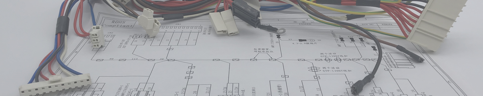
Custom Electronic Component Wire Harness: Precision Cable Assemblies for PCB, Sensors & Industrial Electronics
2026-07-23 16:39Custom Electronic Component Wire Harness: Precision Cable Assemblies for PCB, Sensors & Industrial Electronics
High-Precision Custom Wiring Solutions for Electronic OEMs — From Prototype to Mass Production, Engineered for Signal Integrity, Space Constraints, and Reliability
✓ ISO 9001:2015 Certified | ✓ IPC/WHMA-A-620 Class 2 & 3 | ✓ UL / CE / RoHS / REACH Compliant | ✓ 100% Continuity + Hi-Pot Tested | ✓ Fine-Pitch Connector Expert (JST, Molex, TE, Hirose, JAE, I-PEX) | ✓ Free DFM Review | ✓ 5-Day ECO Turnaround
 Table of Contents
1. Why Electronic Component Harnesses Demand Precision Manufacturing
In modern electronic devices, the wire harness is not just a bundle of cables — it is the nervous system of the product. Whether it's a medical diagnostic device, an industrial PLC controller, a communication base station, or a consumer IoT gateway, the harness carries power, data, and control signals between PCBs, sensors, displays, actuators, and connectors — all within increasingly compact enclosures with ever-tighter performance margins.
Unlike automotive or heavy-equipment harnesses, electronic component harnesses face a distinct set of challenges:
Space constraints: Modern electronics pack more functionality into smaller housings. Harnesses must navigate tight 3D routing paths without exceeding bend-radius limits or pinching.
Signal integrity: High-speed digital signals (USB 3.0, LVDS, MIPI, Ethernet) require controlled-impedance cables, proper shielding, and minimal crosstalk — a single poorly terminated shield can bring down an entire subsystem.
Fine-pitch connectors: 0.5 mm, 0.4 mm, even 0.3 mm pitch connectors from JST, Molex, Hirose, and I-PEX demand precision crimping and wire preparation that commodity harness shops cannot deliver.
Mixed signal types: A single harness often bundles power (up to 48V/20A), analog sensor signals (mV-level), digital communication (I²C, SPI, CAN, RS-485), and high-speed data (USB, Ethernet) — all requiring different wire gauges, shielding strategies, and termination techniques.
Regulatory compliance: Medical electronics require IEC 60601 compliance. Industrial controls need IEC 61010. Communication equipment faces FCC/CE EMC requirements. Every harness in the system contributes to the overall certification picture.
Key insight: The most expensive harness failure in electronics is not a broken wire — it's an intermittent connection that passes electrical test at the factory but fails in the field after thermal cycling, vibration, or humidity exposure. This is why we invest in crimp cross-section analysis, pull-force testing on every connector type, and 100% manual visual inspection — not just automated electrical testing.
We have supplied custom electronic component harnesses to manufacturers of medical devices, industrial automation controllers, test & measurement instruments, communication equipment, security systems, and consumer electronics for over 10 years. Our customers trust us because we understand that in electronics, precision is not optional — it is the baseline.
2. 8 Types of Electronic Component Wire Harnesses We Build
A typical electronic product contains 3–12 distinct harness sub-assemblies. Below are the most common types we manufacture, each with its own wire gauge, connector family, and testing requirements:
| Harness Type | Typical Application | Common Connectors / Wire Spec | Key Manufacturing Requirements |
|---|---|---|---|
| PCB-to-PCB Interconnect Harness | Board-to-board signal and power routing in multi-board systems | JST PH/XH/PA, Molex PicoBlade/Micro-Fit, Hirose DF13/DF52; AWG 22–30 | Precise wire length control (±1 mm), controlled impedance for high-speed lanes, strain relief at PCB entry |
| Sensor & Transducer Harness | Temperature probes, pressure transducers, Hall-effect sensors, photoelectric sensors | M8/M12 circular connectors, TE MATE-N-LOK, Molex Mini-Fit; AWG 20–26, shielded twisted pair | Shield drain-wire termination, IP65/IP67 overmolding, low-noise routing away from power lines |
| Control Panel / HMI Internal Harness | PLCs, touchscreen HMIs, industrial control cabinets | Weidmüller/ Phoenix Contact terminal blocks, D-sub, IDC ribbon; AWG 16–24 | Ferrule crimping for terminal-block entries, wire labeling per customer BOM, bundling with spiral wrap or braided sleeving |
| Display & Touch-Panel Harness | LCD panels, capacitive touch overlays, embedded display modules | I-PEX CABLINE, FPC/FFC adapters, Hirose DF40; AWG 30–36, micro-coaxial | Impedance matching (100 Ω differential), ultra-fine wire stripping (<0.5 mm), anti-static handling throughout assembly |
| Power Distribution Harness | DC power rails from PSU to multiple sub-boards | Molex Mini-Fit/Mega-Fit, Anderson Powerpole, TE VAL-U-LOK; AWG 12–18 | Voltage-drop calculation, UL 1015/1007/1028 wire, secure locking-connector engagement, overcurrent protection integration |
| Communication & Data Bus Harness | RS-485, CAN bus, Ethernet, USB, SPI daisy-chain | RJ45, USB Type-A/B/C, M12 D-coded, Amphenol MIL-DTL; AWG 22–28, CAT5e/CAT6 | 120 Ω termination resistor integration for CAN, 100 Ω differential impedance for Ethernet, shield continuity end-to-end |
| Relay & Contactor Coil Harness | SSR control circuits, contactor coils, solenoid drivers | Faston/Quick-connect terminals, ring terminals, PCB screw terminals; AWG 14–22 | High-temperature insulation (silicone/XLPE) near heat sources, proper crimp for spade/ring terminals, flyback diode integration where needed |
| Battery & Power Management Harness | BMS sense leads, battery pack interconnects, charger harnesses | JST XH/EH, Molex Mini-Fit Jr., custom balance-lead connectors; AWG 16–26 | Cell-voltage accuracy (±1 mV path), fuse integration, color-coded cell numbering, UL/cUL listed wire |
3. Technical Specifications & Industry Standards
Every electronic component harness we manufacture must meet a defined set of electrical, mechanical, and regulatory parameters. Below are the core specifications our engineering team works with daily:
| Parameter | Our Capability Range | Applicable Standard / Note |
|---|---|---|
| Wire Gauge | AWG 36 (0.0127 mm²) ~ AWG 8 (8.37 mm²) | UL 1007, 1015, 1028, 1061, 1569, 2464, 2547, 20234 (high-flex) |
| Insulation Material | PVC, XLPE, Silicone, TPE, PTFE (Teflon), FEP, ETFE | Selected based on temperature class, chemical resistance, and flexibility requirements |
| Operating Temperature | -40°C to +200°C (depending on insulation type) | Silicone and PTFE for high-temp; TPE for cold-flex applications |
| Voltage Rating | Up to 600V AC/DC (standard); up to 1500V DC with special insulation | Hi-Pot tested at 2x rated voltage + 1000V per IPC/WHMA-A-620 |
| Connector Pitch | 0.3 mm (I-PEX) to 7.92 mm (Molex Mega-Fit) | 0.4, 0.5, 0.8, 1.0, 1.25, 1.5, 2.0, 2.5, 2.54, 3.96, 4.2, 5.08, 7.92 mm |
| Connector Brands | JST, Molex, TE/AMP, Hirose, JAE, I-PEX, Amphenol, Samtec, Phoenix Contact, Weidmüller, Harting | Both genuine OEM and cost-optimized equivalents available per customer preference |
| Shielding | Foil (aluminum/mylar), braid (tinned copper), spiral, combination foil+braid | Coverage: 85–98% braid; 100% foil; shield-to-drain-wire termination with solder or crimp sleeve |
| Crimp Type | Open-barrel (B-crimp, F-crimp), closed-barrel, IDC, ultrasonic welding | Crimp height ±0.02 mm tolerance; pull-force ≥ IPC/WHMA-A-620 minimum per wire gauge |
| Impedance Control | 50 Ω single-ended, 100 Ω differential, 75 Ω coaxial | TDR-verified on first-article samples; ±10% tolerance (standard), ±5% (tight) |
| Labeling / Marking | Heat-shrink tube printing, adhesive wrap labels, laser-marked sleeves, ink-jet direct marking | Per customer BOM part number; barcode/QR code option; sequential serial-number tracking |
| Certifications | UL, cUL, CE, RoHS, REACH | CB scheme and TÜV available for medical/industrial per project scope |
| Workmanship Standard | IPC/WHMA-A-620 Class 2 (default), Class 3 (on request) | Class 3 adds tighter acceptance criteria for aerospace, military, and life-support medical applications |
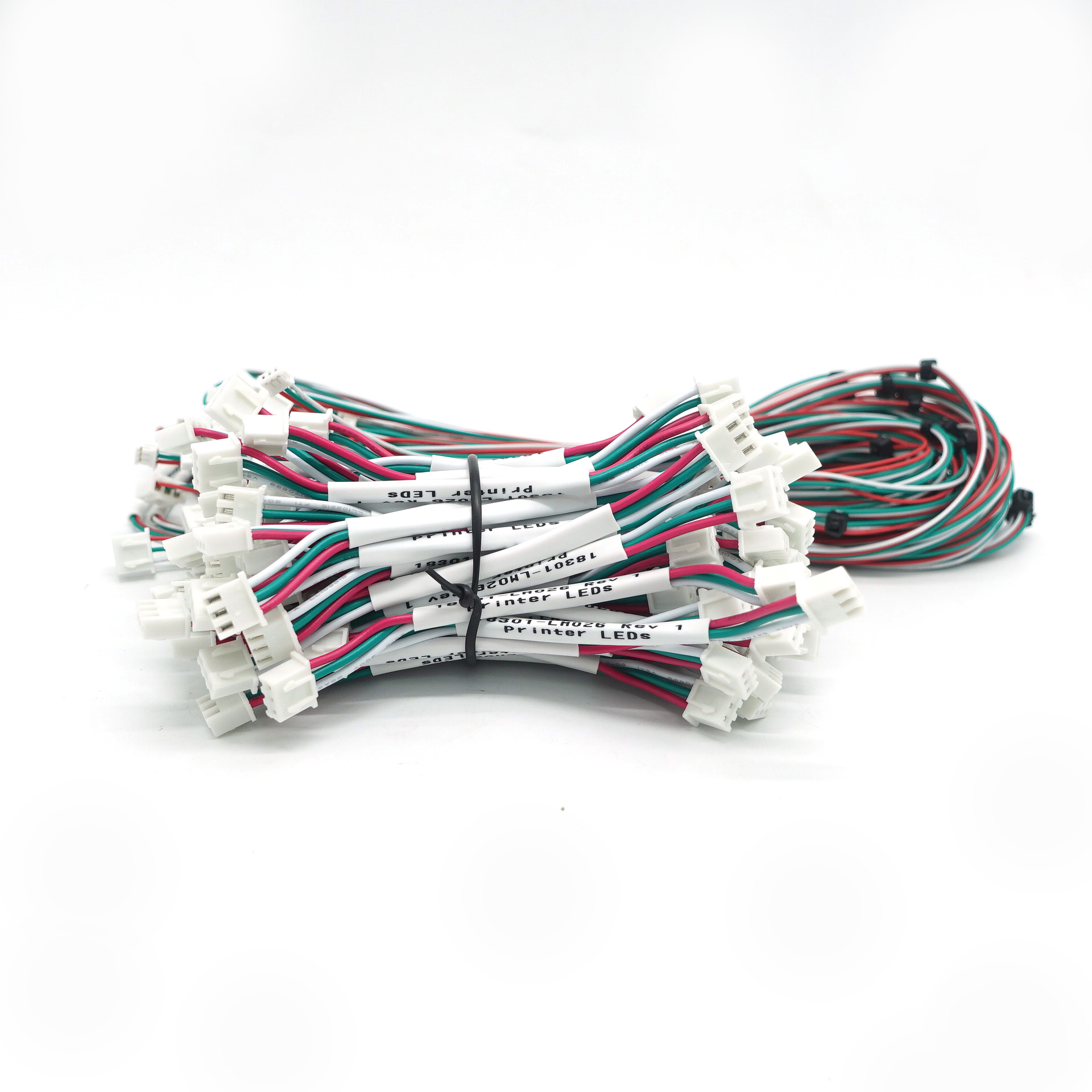
4. 7 Industries That Rely on Custom Electronic Harnesses
The diversity of electronic products means every OEM has unique harness requirements. Here are the key industries we serve and the specific harness challenges in each:
| Industry | Typical Products | Harness Challenge | Our Solution |
|---|---|---|---|
| Industrial Automation | PLCs, servo drives, HMI panels, I/O modules, machine-vision cameras | High pin-count (40–100 pins), mixed power+signal, DIN-rail density constraints, vibration in factory-floor environments | Multi-branch harness design, ferrule crimping for terminal blocks, spiral-wrap bundling, laser-marked wire labels |
| Medical Electronics | Patient monitors, infusion pumps, diagnostic imaging, surgical instruments | IEC 60601 leakage-current limits, biocompatible materials, high-reliability Class 3 solder/crimp, traceability to lot level | Silicone/TPE medical-grade wire, full lot traceability, IPC Class 3 workmanship, ESD-controlled assembly |
| Telecom & Networking | 5G base stations, routers, optical transceivers, edge-computing nodes | High-speed signal integrity, EMI compliance, outdoor IP65/IP67 environmental sealing, compact chassis | Impedance-controlled twisted-pair and coax, 360° shield termination, IP67 overmolded connectors |
| Test & Measurement | Oscilloscopes, spectrum analyzers, data loggers, calibration equipment | Low-noise analog signal paths, precision voltage references, shielded internal routing, flex-zone cable management | Star-ground wiring topology, individually shielded twisted pairs, PTFE low-dielectric wire, gold-plated contacts |
| Security & Access Control | Access controllers, biometric readers, surveillance NVRs, alarm panels | Tamper-detection circuits, backup-battery harnesses, multi-door wiring complexity, UL 294 / EN 50131 compliance | Tamper-loop integration, fused battery harnesses, multi-branch door-controller harnesses with labeled zone wiring |
| Smart Building & IoT | Smart thermostats, lighting controllers, occupancy sensors, energy monitors | Miniaturization, low-power sensor interfaces, wireless antenna coax, consumer price sensitivity without quality compromise | Fine-pitch micro-connectors, micro-coaxial RF jumpers, cost-optimized connector equivalents, automated wire prep |
| Power Electronics | Inverters, converters, UPS systems, EV chargers, solar MPPT controllers | High current (20A–200A), high voltage (up to 1500V DC), thermal management of bus-bar connections, creepage/clearance per IEC 60664 | UL 10269 heavy-wall wire, double-insulated HV cables, torque-specified ring-terminal crimping, silicone boots over bus-bar connections |
5. Our Custom Manufacturing Capabilities for Electronics OEMs
When you develop a new electronic product, your harness supplier should be an engineering partner, not just an order-taker. Here is what our factory brings to every project:
| Capability | What We Do | Why It Matters to You |
|---|---|---|
| Free DFM (Design for Manufacturability) Review | Our engineers analyze your drawing/BOM and flag potential issues: wire gauge mismatch, connector-pitch accessibility, strain-relief gaps, shield termination ambiguity, and routing conflicts — before we build anything. | Catches 90% of production issues during the quoting phase. Saves weeks of back-and-forth prototyping. |
| ECO (Engineering Change Order) — 5-Day Turnaround | Need to swap a connector, change a wire length, or add a branch? We process ECOs in 5 business days — no penalty, no drama. | Electronics designs evolve fast. Your supplier should keep up, not slow you down. |
| Multi-Variant BOM Management | One product family, 12 SKU variants with different connector options, wire lengths, and shielding? We manage the entire matrix, keeping each variant's BOM, test fixture, and QC checklist distinct and traceable. | You ship one build instruction. We handle the rest. |
| Custom Wire Color & Labeling | We match your wiring diagram exactly: solid, striped, or spiral-tracer colors; laser-printed heat-shrink labels with part numbers, pin numbers, and serial codes per wire. | Field-service technicians can trace every wire without a multimeter. |
| Overmolding & Strain Relief | Low-pressure overmolding (PVC or TPE) at connector back-shells, Y-junctions, and PCB entry points. IP65/IP67 sealing where needed. | Prevents the #1 field failure in electronics: broken wires at the connector back-shell. |
| Pre-Terminated Kits & Ready-to-Install Assemblies | We deliver fully terminated harnesses in labeled bags by sub-assembly, with a QR-coded checklist. Your assembly line opens the bag and plugs it in. | Eliminates on-site crimping errors, reduces assembly labor by 40-60%. |
| Protective Sleeving & Bundling | Braided expandable sleeving, spiral wrap, corrugated conduit, heat-shrink tubing, custom fabric sleeves — selected for your product's internal environment. | Protects wires from abrasion in tight chassis and maintains serviceability. |
| Full Traceability | Every harness is serialized. We track: raw wire spool lot number, connector batch, crimp tooling ID, operator ID, test date, and test results — archived for 3+ years. | When an audit or field failure investigation happens, you have data, not guesses. |
| Kanban / Safety-Stock Programs | For recurring production orders, we maintain 2–4 weeks of finished-goods safety stock and ship on a pull signal. | Zero production downtime because of harness shortages. |
6. Common Failure Modes & How We Prevent Them
After manufacturing millions of electronic harnesses, we have identified the recurring failure patterns — and built systematic prevention into our process:
| Failure Mode | Root Cause | Consequence | Our Prevention Method |
|---|---|---|---|
| Intermittent Connection | Under-crimped terminal, loose pin retention, cold solder joint at shield drain | Random device reboots, signal dropouts, field return nightmares | Crimp-height measurement on every setup change; pull-force test on first-piece and hourly samples; 100% continuity test on every harness |
| Broken Wire at Connector Back-Shell | No strain relief; harness bent sharply at connector exit during installation | Open circuit after weeks/months of vibration | Overmolded strain relief or heat-shrink boot at every connector exit; minimum bend-radius spec on assembly drawing |
| EMI / Cross-Talk on Sensor Lines | Unshielded sensor wires routed parallel to high-current PWM or switching-power traces | Noisy ADC readings, false sensor triggers, product failing EMC compliance tests | Shielded twisted-pair for all analog sensor signals; shield terminated at one end only (source-end grounding); physical separation from power wires in bundle |
| Connector Pin Mis-Insertion | Operator error during manual connector assembly; no poke-yoke fixture | Short-circuit on power-up, PCB damage, reverse-polarity failures | 100% pin-to-pin electrical test against golden-unit fixture; visual inspection with connector-face diagram on QC checklist |
| Insulation Damage (Nicked/Burned Wire) | Over-aggressive mechanical stripping or incorrect heat-shrink temperature | Latent short-circuit risk; reduced dielectric strength | Precision pneumatic stripping machines with blade-depth control; temperature-calibrated heat guns; 100% visual inspection of every stripped end under magnification |
| Wrong Wire Gauge or Insulation in Build | Material mix-up at wire-preparation station | Overheating on current-carrying wires; regulatory non-compliance | Barcode-scanned wire spool verification before cutting; color-coded wire racks per BOM; in-process audit every 2 hours |
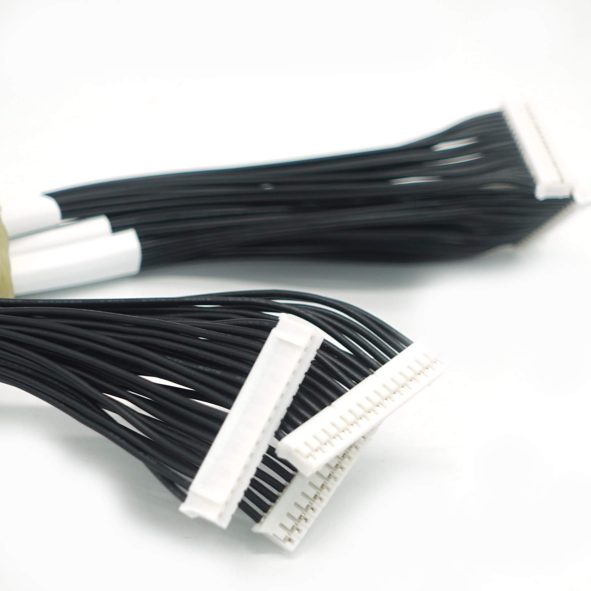
7. Quality Testing & 100% Manual Inspection
In electronic component harness manufacturing, automated testing catches continuity faults — but only human inspection catches the subtle issues that cause field failures: a partially inserted terminal, a shield drain wire with one broken strand, a heat-shrink tube that didn't fully recover, a label that is slightly crooked and will peel off after 1,000 thermal cycles.
This is our quality assurance process for every harness:
| # | Test / Inspection | Equipment Used | What We Check | Frequency |
|---|---|---|---|---|
| 1 | 100% Continuity / Pin-Map Test | Custom pin-map test fixture (Cirris / Dynalab or in-house built) | Every pin-to-pin path for continuity; every non-connected pin pair for shorts; diode polarity; resistor value where applicable | Every harness |
| 2 | Hi-Pot / Dielectric Withstand Test | Programmable hipot tester (AC/DC up to 5 kV) | Leakage current between isolated circuits at 2× rated voltage + 1000V; arc detection | Every harness where isolation is safety-critical |
| 3 | Insulation Resistance (IR) Test | Megohmmeter / IR tester (500V or 1000V DC) | Resistance between isolated conductors; minimum threshold per IPC/WHMA-A-620 (typically ≥ 100 MΩ at 500V DC) | Sampling (AQL 0.65) or 100% per customer spec |
| 4 | Crimp Pull-Force Test | Digital force gauge with dedicated grip fixtures | Pull-force per wire gauge per IPC/WHMA-A-620 Table 9-1 (e.g., AWG 26 ≥ 13.3 N, AWG 20 ≥ 44.5 N) | First-piece of every batch + hourly in-process sample |
| 5 | Crimp Cross-Section Analysis | Metallurgical cut-and-polish station + digital microscope | Compression ratio (15–20% area reduction), conductor deformation, bellmouth, cut-off tab length, insulation grip | First-piece validation of every new crimp die setup; periodic audit |
| 6 | 100% Manual Visual Inspection | Magnifying lamp (3×–5×), digital microscope for fine-pitch | Terminal insertion depth, latch engagement, wire color correctness, label position & legibility, heat-shrink recovery, shield solder quality, no nicks/burns on insulation, proper sleeving coverage, connector back-shell tightness | Every harness |
| 7 | Dimensional Check | Steel rule, digital caliper, go/no-go gauge, pin-gauge for connector cavities | Overall length, branch lengths, connector-to-connector distances, breakout positions | First-piece + random sampling per AQL 1.0 |
| 8 | First-Article Inspection Report (FAIR) | Full test report package | Complete dimensional, electrical, and visual results against drawing and BOM — documented in PDF with photos | Once per new part number, before mass production release |
✅ Our quality data: First-pass electrical test yield typically exceeds 99.95%. Customer field return rate (RMA) for electronic harnesses: < 0.05% over the past 3 years.
8. How We Work: From Drawing to Delivery in 6 Steps
| Step | Phase | What Happens | Who Does It | Duration | Deliverable |
|---|---|---|---|---|---|
| 1 | Inquiry & RFQ | You send: drawing (PDF/DWG/STEP), BOM, target quantity, and any special requirements. We review for completeness and ask clarifying questions. | Sales Engineer + You | 1–2 business days | Complete requirements checklist |
| 2 | DFM & Engineering Review | Our engineers analyze your design: wire gauge adequacy, connector accessibility, strain-relief needs, shielding strategy, testability. We send you a DFM report with recommendations. | Process Engineer | 2–3 business days | DFM report (free) |
| 3 | Quotation | We provide a detailed quote breaking down: raw materials (wire, connectors, sleeving, labels), labor (cut, strip, crimp, assemble, test), tooling (if new crimp dies or test fixtures needed), NRE, and unit price at multiple quantity tiers. | Sales Engineer | 2–3 business days | Detailed quotation |
| 4 | Prototype & First Article | We build 5–50 prototype pieces with full documentation. Each is 100% tested and visually inspected. We ship with a FAIR report including test data and photos. | Production Team + QC | 5–10 business days | Prototype samples + FAIR |
| 5 | Production | Full production run with in-process QC checks at every workstation. Pin-map test fixture guards every harness. QC performs sampling inspections per AQL 1.0. | Production + QC | Per order volume (typically 2–4 weeks) | Production units + inspection reports |
| 6 | Packing & Shipment | Harnesses are individually bagged, labeled with part number and serial, packed with desiccant and ESD protection, and shipped with full documentation. | Logistics Team | 1–3 business days | Packed shipment + docs |
9. Frequently Asked Questions
Q1: Can you handle fine-pitch connectors like I-PEX 0.4 mm or Molex PicoBlade 1.25 mm?
Yes. We regularly work with ultra-fine-pitch connectors down to 0.3 mm (I-PEX CABLINE series). Our operators use digital microscopes for terminal insertion verification, and we have dedicated crimp tooling calibrated for these miniature contacts. If you are unsure whether a connector is manufacturable, send us the drawing — we will tell you honestly.
Q2: We have a product with 50+ wires in a tight chassis. Can you build complex multi-branch harnesses?
Absolutely. Multi-branch harnesses with 40–120 wires and 5–15 connector endpoints are our daily work. We build custom pin-map test fixtures that verify every branch simultaneously, so a 50-wire harness is tested in one pass — not sequentially.
Q3: What's your minimum order quantity (MOQ) for custom electronic harnesses?
For prototype and small-batch orders, we accept quantities as low as 10–50 pieces. For ongoing production, typical MOQs range from 100–1,000 pieces depending on complexity. We understand that electronic products go through low-volume pilot runs before scaling — we support that transition.
Q4: We need UL-listed wire and connectors. Can you provide UL traceability?
Yes. All UL-listed wires, connectors, and sleeving we use come with full traceability to the UL file number. We can provide UL component certificates with every shipment. If your product requires UL recognized-component (UR) or UL listed end-product certification, we will work with your compliance team to supply the documentation your NRTL needs.
Q5: What if our drawing has mistakes — wrong connector orientation, impossible wire routing, missing dimensions?
This is exactly why we offer free DFM review. Our engineers catch these issues before any material is cut. We will flag every concern, suggest practical alternatives, and only proceed after your approval. We have seen thousands of drawings — we know where the problems hide.
Q6: How fast can you turn around an engineering change (ECO)?
We process ECOs in 5 business days from approval. This covers: updated BOM review, new material procurement (if needed), fixture modification, documentation update, and first-piece validation. Rush ECOs can be accommodated in 2–3 days for critical issues.
Q7: Do you offer consignment stock or VMI (vendor-managed inventory)?
Yes. For ongoing production relationships, we maintain 2–4 weeks of finished-goods safety stock and ship on demand. We can integrate with your ERP/MRP system through EDI or simple email-based pull signals. Your assembly line never waits for harnesses.
10. Start Your Electronic Component Harness Project
Whether you are prototyping a new electronic product, scaling from pilot to mass production, or looking for a more reliable harness supplier who understands electronics — we are ready to support you.
What to send us for a quote:
Drawing or sketch — PDF, DWG, STEP, or even a hand-drawn sketch with dimensions
BOM (Bill of Materials) — wire gauges, connector part numbers, labels, sleeving types
Target quantity — prototype batch or annual volume forecast
Any special requirements — IPC Class, regulatory standards, environmental conditions, packaging preferences
What you'll get back within 3 business days:
✅ Free DFM review with actionable engineering feedback
✅ Detailed quotation with material, labor, and tooling breakdown
✅ Lead-time estimate for both prototypes and production volumes
✅ Honest assessment of any manufacturability concerns
✉ Ready to Discuss Your Electronic Harness Project?
Send us your drawing and BOM. We'll return a free DFM review and quotation within 3 business days.
✉ Send Your Drawing & BOMOr visit: www.xmkehan.com | ISO 9001:2015 | IPC/WHMA-A-620 | UL / CE / RoHS / REACH