


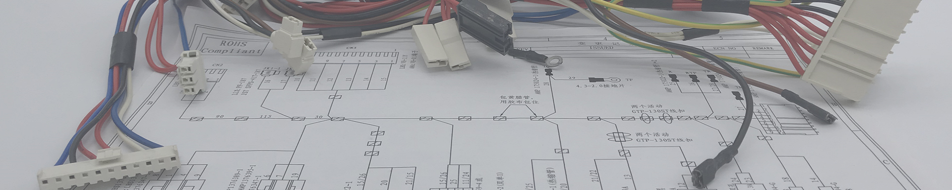
Custom Battery Pack Wire Harnesses
2026-08-07 15:45Custom Battery Pack Wire Harnesses & Connection Solutions — Built by a Factory That Understands Power
We design and manufacture battery connection harnesses, BMS sensing leads, cell interconnects, and custom cable assemblies for battery pack manufacturers worldwide. From 3-cell LiPo balance leads to 400V energy storage arrays.
ISO 9001:2015 Certified | UL / CE / UN38.3 / IEC 62133 Compatible | IPC/WHMA-A-620 Class 2 & 3 | 100% Electrical + Hi-Pot Tested | Free DFM Review
1. The connection is the battery's weakest link
A battery pack is only as reliable as its weakest connection. You can have the best cells in the world — LG, Samsung, Panasonic, CATL — but if the BMS sensing harness has a cold crimp on cell 7, your voltage monitoring is wrong. If the interconnect between two parallel groups has high resistance, one group does more work than the other, ages faster, and takes the whole pack down with it. If the main discharge leads undersized for the application, the insulation softens, resistance climbs, and you have a thermal event on your hands.
We see this all the time. A customer comes to us with a battery pack that failed field testing. The cells are fine. The BMS chip is fine. The protection circuit works. But the wiring harness — sourced from the cheapest supplier they could find on Alibaba — has a terminal that backed out of its housing during vibration testing. Or a balance lead with a wire that was nicked during stripping and partially severed, creating a high-resistance path that the BMS reads as an over-voltage condition on one cell.
These are not exotic failure modes. They are basic manufacturing defects that a competent wire harness factory should never produce. But the battery industry has a problem: most wire harness factories do not understand batteries. They do not know why a BMS sensing lead needs to be within ±1 mV accuracy. They do not know why you cannot run a balance wire parallel to a high-current busbar. They do not know the difference between a cell-level fuse wire and a regular signal wire.
We do. We have been building battery connection harnesses for over a decade — for power tool packs, e-bike batteries, portable power stations, medical device battery packs, drone packs, and grid-scale energy storage systems. This article covers what we have learned, what we build, and why the harness inside your battery pack deserves more attention than it usually gets.
2. What lives inside a battery pack — the wiring breakdown
A modern battery pack is not just cells in a box. It is an electrical system with multiple subsystems, each with different current, voltage, and signal requirements. Here is what we typically build for a custom battery pack:
| Harness subsystem | What it does | Typical connectors & wire | Manufacturing challenges |
|---|---|---|---|
| Main power discharge leads | Carries full pack current from the battery to the load (motor, inverter, device) | XT90/XT150, Anderson SB/SB, custom high-current lug terminals; AWG 8–2/0 silicone wire | High-current crimping (100–300A continuous), heat-shrink strain relief, UL 10269 compliance for HV |
| BMS cell-voltage sensing harness | Connects each cell or parallel group to the BMS for voltage monitoring and balancing | JST XH/EH/PH, Molex PicoBlade; AWG 24–28, color-coded per cell position | ±1 mV path accuracy, wire length matching across all sensing lines, color coding consistency |
| Temperature sensor (NTC) harness | Routes NTC thermistor signals from cell surfaces to the BMS for thermal monitoring | JST PH, custom inline NTC sensor pods; AWG 26–28, shielded optional | Sensor placement accuracy, thermal interface material compatibility, wire routing away from heat sources |
| Cell interconnect / balance bar | Parallel cell connection within a group (wire, nickel strip, or busbar) | Spot-welded nickel strip, ultrasonic-welded wire, or laser-welded busbar; AWG 14–20 equivalent | Resistance matching across parallel paths, weld quality consistency, thermal expansion accommodation |
| Protection circuit (PCM/BMS) interconnects | Connects the BMS PCB to the MOSFET/contactor gate drives, current shunt, and protection circuit | Board-to-board, FFC/FPC, fine-pitch connectors; AWG 22–30 | Vibration resistance in mobile packs, connector locking mechanism, service accessibility |
| Communication harness | Carries data between the battery and the host device (CAN bus, RS485, SMBus, I2C) | M8/M12 circular, RJ45, CAN bus J1939; AWG 22–26, twisted pair with shield | 120Ω impedance matching, shield continuity, ground-loop isolation |
| Charging input harness | External charge port to BMS/PCM charging input | DC barrel jack, USB-C PD, custom magnetic connector; AWG 16–22 | Reverse-polarity protection, overcurrent fuse integration, connector durability (5,000+ cycles) |
| Cell-level fuse wire (where applicable) | Individual fuse wire on each cell in high-reliability packs (aerospace, medical) | Arc-fuse wire, thermal fuse wire; AWG 28–32, specific alloy | Fuse rating precision, weld quality, isolation from adjacent cells |
3. BMS sensing harnesses — where precision matters most
If there is one harness in a battery pack that we obsess over, it is the BMS sensing harness. This is the bundle of thin wires that connects each cell (or parallel group) to the battery management system's ADC inputs. The BMS uses these voltage readings to:
Monitor individual cell voltages for over-voltage and under-voltage protection
Trigger cell balancing during charging
Calculate state-of-charge (SOC) and state-of-health (SOH)
Detect cell-level anomalies that could indicate thermal runaway
If any sensing wire has higher resistance than the others — due to a bad crimp, a nicked conductor, or a wire that is significantly longer than its neighbors — the BMS reads a voltage drop on that cell. It looks like the cell is under-charged or under-loaded. The BMS may trigger unnecessary balancing, reduce pack performance, or shut down the pack entirely. In a worst case, a missing or broken sensing wire causes the BMS to lose visibility of a cell entirely — which means no over-voltage protection on that cell during charging. That is how thermal runaway starts.
Here is how we build BMS sensing harnesses to avoid these problems:
Wire length matching. Every sensing lead in a given harness is cut to the same length (within ±2 mm), even if the physical routing distance to each cell is different. The excess is managed with a service loop, not by trimming some wires shorter. This ensures equal resistance across all sensing paths. If the BMS datasheet specifies a maximum lead resistance (typically 10–50 mΩ), we calculate the maximum allowable wire length and never exceed it.
Color coding. Every cell position gets a unique wire color. For packs with many cells (14S, 16S, 24S), we use striped wire (red/black, white/black, blue/black, etc.) to expand the color palette. This is not just for aesthetics — it prevents the assembler from inserting a sensing wire into the wrong connector cavity, which would feed the wrong cell voltage to the wrong BMS pin. We verify the color sequence against the customer's BOM on every production run.
Crimp quality on fine-pitch terminals. BMS sensing connectors are small. JST XH (2.5 mm pitch), JST PH (2.0 mm), Molex PicoBlade (1.25 mm). The terminals are tiny. The wire is thin (AWG 26–28). A crimp that looks acceptable to the naked eye can still be loose enough to cause intermittent contact after vibration. We crimp these with calibrated pneumatic tooling, verify crimp height with a micrometer on every setup, and pull-test samples every hour. We also perform a 100% pin-map continuity test on every finished harness — if a terminal is not fully seated in the housing, the test catches it.
Routing away from high-current paths. Inside a battery pack, the main power bus carries dozens or hundreds of amps. The magnetic field around that bus can induce noise on nearby sensing wires. We route sensing harnesses along the edge of the pack, away from busbars and interconnects. For high-noise environments (motor controllers nearby, switching converters), we offer shielded sensing harnesses with the shield grounded at the BMS end only.
4. Cell interconnects — more than just nickel strip
When people think about cell-to-cell connections in a battery pack, they usually picture nickel strip spot-welded to 18650 or 21700 cells. That is the most common method for consumer-grade packs, and it works fine for moderate currents. But when you move to higher-power applications — power tools, e-bikes, drones, energy storage — the interconnect strategy needs to evolve.
| Method | Current capacity | How it works | When to use it |
|---|---|---|---|
| Nickel strip, spot-welded | 5–15A per strip | 0.1–0.15 mm pure nickel strip, resistance spot-welded to cell terminals. Can layer strips for higher current. | Consumer electronics, low-power packs, cost-sensitive applications. The default for most 18650/21700 packs under 10A continuous. |
| Nickel-plated steel strip | 3–8A per strip | Cheaper than pure nickel, higher resistance. Common in budget packs. | We do not recommend this for any application where reliability matters. The higher resistance generates heat, which degrades the cell-terminal weld over time. If you are building a quality product, use pure nickel or one of the alternatives below. |
| Wire interconnect, ultrasonic-welded | 15–50A depending on wire gauge | Stranded copper wire (AWG 14–18), ultrasonically welded to cell terminals. Lower resistance than nickel strip, more flexible. | E-bike batteries, power tool packs, drone packs. Better current handling than strip, accommodates thermal expansion and vibration. |
| Copper busbar, laser-welded | 100–500A+ | Solid copper busbar (0.5–3 mm thick), laser-welded to cell terminals. Lowest resistance, highest current capacity. | EV battery modules, grid-scale energy storage, high-power industrial packs. Requires laser welding equipment — we partner with facilities that have this capability. |
| Flexible printed circuit (FPC) interconnect | 3–10A per trace | Polyimide-based flexible circuit with copper traces, bonded to cell terminals via conductive adhesive or welding. | Ultra-thin packs (wearables, slim devices) where wire harnesses are too bulky. We design and source FPC interconnects through our partner network. |
We build wire-based interconnects in-house using ultrasonic welding. For nickel strip and busbar applications, we design the interconnect layout and partner with specialized welding facilities for the actual cell-level welding. Either way, we manage the full interconnect specification — material, dimensions, weld parameters, and inspection criteria.
5. Connectors for battery applications — what we recommend and why
Battery connectors are not generic. The connector you choose for a 3S LiPo drone pack is fundamentally different from what you need on a 400V industrial energy storage module. Here is our practical guidance based on what has worked (and what has failed) across hundreds of battery projects:
| Connector | Current / Voltage | Typical application | Our experience notes |
|---|---|---|---|
| XT60 / XT90 | 60A / 90A continuous, up to 600V | RC packs, portable power stations, small e-bike batteries | Reliable, widely available, easy to assemble. Genuine Amass XT connectors have gold-plated contacts and consistent spring force. We use genuine Amass only — the copies have inconsistent contact geometry and will arc under high current. |
| Anderson Powerpole (15/30/45/75) | 15A – 75A per blade, stackable | Ham radio, DIY solar, modular battery systems | Modular and color-coded. We like these for systems where the user frequently connects and disconnects the battery. Contact wiping action on mating keeps the surfaces clean. |
| Amphenol SurLok Plus | Up to 250A, 1000V DC | Energy storage systems, EV charging, industrial power | Rugged, keyed, IP2X finger-safe. Our go-to for high-voltage DC battery connections where safety is paramount. Touch-safe contacts are critical for 400V+ systems. |
| M8 / M12 circular (A/D/S coded) | Signal / data, up to 4A per pin | BMS communication (CAN, RS485), sensor connections | IP67 rated, vibration-proof, twist-lock mechanism. For communication between the battery and the host system, M12 D-coded (Ethernet/CAN) is our standard recommendation. More expensive than RJ45 but survives vibration and moisture. |
| JST XH / EH / PH | 3A / 5A, signal-level | BMS sensing leads, balance connectors, NTC thermistor leads | The standard for cell-level sensing connections. We use genuine JST terminals — the difference in contact retention force between genuine and copy terminals is measurable and significant. A copy terminal may back out after 50 mate/demate cycles; genuine JST holds for 500+. |
| Custom / semi-custom | Varies | Proprietary battery systems, white-label OEM packs | Some battery manufacturers have their own connector design. We can source and assemble proprietary connectors under NDA. If the connector volume justifies it, we can also facilitate custom tooling. |
6. Wire and insulation specifications — why material choice is not optional
The wire inside a battery pack operates in a more hostile environment than most people realize. It is enclosed in a small space with cells that can reach 60°C during discharge. It is subjected to vibration in mobile applications. It may be exposed to electrolyte vapor if a cell vents. And in high-voltage packs, it must maintain dielectric integrity at hundreds of volts for the life of the product.
| Wire insulation | Temp range | Voltage rating | Best for | Limitations |
|---|---|---|---|---|
| PVC (UL 1007/1015) | -20°C to +80°C (105°C) | 300V | Low-voltage signal wires, BMS sensing leads in consumer packs | Melts above 105°C. Not suitable for high-current power leads or high-temp environments. We avoid PVC for any wire that carries more than 5A inside a battery enclosure. |
| Silicone (UL 3123/3302) | -60°C to +200°C | 300V – 600V | Main power leads, motor/ESC connections, high-discharge packs | Excellent flexibility and heat resistance. More expensive than PVC and slightly more fragile to mechanical abrasion. Our default choice for any current-carrying wire inside a battery pack. |
| XLPE (UL 3386/10269) | -40°C to +125°C | 300V – 1000V | High-voltage battery interconnects, EV packs, energy storage | Good dielectric strength, mechanically tough, resists deformation under compression. Less flexible than silicone — harder to route in tight spaces. Required for 600V+ systems. |
| PTFE/Teflon (UL 1180/1213) | -70°C to +260°C | 250V – 600V | Sensor wires in extreme environments, aerospace packs, medical battery packs | Exceptional temperature range and chemical resistance. Expensive. Thin wall saves space but makes the wire delicate during assembly. Reserved for applications that genuinely need it. |
| TPE (thermoplastic elastomer) | -40°C to +105°C | 30V – 300V | Consumer device battery packs, wearable batteries | Soft, flexible, skin-safe for wearable applications. Lower temperature and voltage rating than silicone. Common in consumer electronics where RoHS/reach compliance and flexibility matter more than thermal performance. |
For high-voltage battery packs (above 60V DC, which is the threshold for "dangerous voltage" per most safety standards), we follow these rules:
Orange insulation on all HV conductors (international convention for HV wiring)
Double-wall insulation (insulation + jacket) on all HV wires
Minimum creepage and clearance distances per IEC 60664-1
Hi-Pot test at 2× rated voltage + 1000V on every harness
Interlock loop that disconnects the contactor if the harness is unplugged
7. Safety features we can integrate into your battery harness
A battery harness is not just wire and connectors. It can — and in many cases should — include active safety components. Here are the features we commonly integrate:
Fuse integration. For packs with multiple parallel strings, we can integrate a fuse wire or fuse holder on each string's main output. If one string shorts internally, the fuse isolates it from the rest of the pack. Fuse rating is selected based on the normal operating current and the trip-time curve.
Thermal fuse / thermal cutoff. A one-shot thermal fuse embedded in the harness, placed against the hottest cell group. If the temperature exceeds the fuse rating (typically 70°C–90°C), the fuse opens permanently, cutting the discharge path. This is a last-resort safety device that operates independently of the BMS.
Interlock loop. A sensing loop that runs through the connector housing. If the connector is partially unplugged, the loop breaks and the BMS (or contactor driver) immediately disconnects the main contactor. This prevents arcing during hot-plug operations on high-voltage packs.
Pre-charge circuit wiring. For packs driving capacitive loads (motor controllers, inverters), the inrush current at connection can be enormous. We build harnesses that include a pre-charge resistor path — the BMS closes the pre-charge contactor first, limits inrush current through a resistor, then closes the main contactor after the bus voltage equalizes.
Current shunt wiring. Some BMS designs use an external current shunt (precision resistor) for coulomb counting. The sense leads from the shunt to the BMS must be a twisted pair, routed away from the main current path, and terminated with Kelvin (4-wire) connections at the shunt. We build these per the BMS manufacturer's application note.
8. Industries we serve with battery harness solutions
| Industry | Typical battery products | Key harness challenges | What we deliver |
|---|---|---|---|
| Consumer electronics | Power banks, laptop battery packs, portable speakers, smart home devices | Space constraints, low cost, RoHS compliance, mass-production consistency | Thin-wall wire, fine-pitch BMS connectors, automated wire prep, 100% electrical test |
| E-mobility | E-bike, e-scooter, e-skateboard, hoverboard, one-wheel packs | Vibration, outdoor exposure, high discharge current, UN38.3 transport compliance | Silicone power leads, IP65 overmolded connectors, vibration-resistant crimps, fuse integration |
| Power tools | Cordless drill, saw, grinder battery packs (18V–36V platforms) | High burst current (100A+), drop-resistance, frequent connect/disconnect cycles | Heavy-gauge silicone wire, reinforced strain relief, durable contact plating, 5000+ cycle connectors |
| Energy storage | Home BESS, commercial storage, grid-scale battery cabinets (48V–1500V) | High voltage, long lifetime (10+ years), UL 1973/IEC 62619 compliance, large cell counts (16S–48S) | XLPE HV wire, Amphenol SurLok connectors, interlock loops, pre-charge harness, full traceability |
| Drones & UAVs | Quadcopter, fixed-wing UAV, agricultural drone packs (6S–14S LiPo) | Weight minimization, high discharge (50C+), EMI from ESC/motor, crash survivability | Thin-wall silicone, XT90/AS150 connectors, shielded sensing leads, weight-optimized routing |
| Medical devices | Portable defibrillator, infusion pump, surgical tool battery packs | IEC 60601 compliance, biocompatible materials, full traceability, Class 3 workmanship | Medical-grade silicone wire, serialized harnesses, IPC Class 3 crimps, lot-level traceability |
| Industrial equipment | UPS systems, AGV/AMR battery packs, backup power, robotics | 24/7 operation, high cycle life, integration with CAN bus systems, DIN-rail packaging | CAN bus communication harnesses, heavy-duty connectors, temperature sensor arrays, serviceable harness design |
9. Our manufacturing capabilities
We are not a battery pack assembler. We are a wire harness factory that specializes in the connections inside battery packs. Here is what that means in practice:
| Capability | What we do | Why it matters for your battery project |
|---|---|---|
| Free DFM review | Our engineers review your battery schematic, BMS datasheet, and mechanical layout. We flag wire gauge concerns, connector compatibility issues, routing conflicts, and sensing-lead length mismatches — before we cut any wire. | Saves 2–4 weeks of prototype iterations. Most BMS sensing harness problems are design issues, not manufacturing issues. |
| 5-day ECO turnaround | Change a connector, add a temperature sensor, extend a wire? We process engineering changes in 5 business days. | Battery designs change frequently during prototyping. Your harness supplier should not be the bottleneck. |
| Multi-variant BOM management | One battery platform, 8 capacity variants (different cell counts, different connectors, different BMS)? We manage the full matrix — each variant has its own BOM, test fixture, and QC checklist. | You issue one build order per SKU. We handle the rest. |
| Custom test fixtures | For every new battery harness design, we build a pin-map test fixture that mates with your connectors and verifies every cell-sensing path, every temperature sensor, and every communication line in one pass. | 100% electrical test in seconds, not minutes. Critical for high-volume battery pack production. |
| Ultrasonic welding | For wire-based cell interconnects, we have in-house ultrasonic welding capability. This is superior to soldering for battery interconnects — no heat damage to cell seals, lower contact resistance, and more consistent joints. | Direct control over interconnect quality without relying on a third-party welding vendor. |
| Overmolding | Low-pressure PVC/TPE overmolding at connector back-shells and branch junctions. IP65/IP67 rated options for outdoor and marine battery applications. | Prevents wire fatigue at connector exits. Essential for e-bike, marine, and outdoor energy storage packs. |
| Full traceability | Every harness is serialized. Wire spool lot, connector batch, crimp tooling ID, operator, test date, and test results are archived for 3+ years. | When a field return comes in, you can trace the harness back to the exact material lot and production shift. |
| Kanban / safety stock | For production battery programs, we maintain 2–4 weeks of finished-goods stock and ship on demand. | Your battery assembly line never stops because of a harness shortage. |
10. Quality testing — every harness, every time
Battery harnesses are safety-critical components. A failure is not just a warranty issue — it can be a thermal event. Our testing protocol reflects that:
| # | Test | What we check | Equipment | Frequency |
|---|---|---|---|---|
| 1 | 100% pin-map continuity | Every cell-sensing pin, every power path, every communication line — verified for continuity and correct pin assignment. Shorts between adjacent pins detected simultaneously. | Custom pin-map fixture + Cirris/Dynalab tester | Every harness |
| 2 | Hi-Pot / dielectric withstand | Leakage current between isolated circuits (power vs. sensing, power vs. communication) at 2× rated voltage + 1000V. Arc detection. | Programmable hipot tester (AC/DC up to 5kV) | Every harness in HV packs |
| 3 | Insulation resistance | Resistance between isolated conductors at 500V or 1000V DC. Minimum 100 MΩ per IPC/WHMA-A-620. | Megohmmeter | Sampling (AQL 0.65) or 100% per spec |
| 4 | Crimp pull-force | Pull-force per wire gauge per IPC/WHMA-A-620 Table 9-1. Each terminal type tested on first-piece and hourly. | Digital force gauge with grip fixture | First-piece + hourly |
| 5 | Crimp cross-section | Compression ratio, conductor deformation, bellmouth, insulation grip — verified under microscope. | Cut-and-polish station + digital microscope | Every new die setup |
| 6 | 100% manual visual inspection | Terminal seating depth, latch engagement, wire color sequence, heat-shrink recovery, solder joint quality, sleeve coverage, label legibility. | Magnifying lamp (3x–5x), digital microscope for fine-pitch | Every harness |
| 7 | Dimensional check | Overall length, branch lengths, breakout positions, connector-to-connector distances. | Calibrated measuring board, digital caliper | First-piece + random sampling |
| 8 | First-article inspection report | Complete dimensional, electrical, and visual results with photos — documented in PDF. | Full test report package | Once per new part number |
Our first-pass electrical test yield on battery harnesses exceeds 99.9%. Customer RMA rate for battery harnesses over the past 3 years: less than 0.03%.
11. How to start your battery harness project
Whether you are prototyping a new battery pack, scaling to mass production, or looking for a more reliable harness supplier for an existing product, here is how to get started:
Step 1: Send us your documentation.
Battery pack schematic (cell configuration: 3S, 7S, 14S, 24S, etc.)
BMS datasheet or pin-out table
Mechanical layout (if available) showing cell arrangement and BMS board location
Connector preferences (or ask us to recommend)
Target quantity (prototype, pilot, or production volume)
Any applicable safety standards (UL 1973, IEC 62133, UN38.3, IEC 60601, etc.)
Step 2: We do a free DFM review. Our engineer analyzes your design and sends feedback within 1–2 business days. We flag any issues we see and suggest practical solutions. No cost, no obligation.
Step 3: You receive a detailed quote. Material breakdown, labor, tooling (if any), and unit pricing at multiple quantity tiers. Lead time estimate for prototypes and production.
Step 4: Prototype samples. We build 5–50 pieces. You test them in your actual battery pack. If adjustments are needed, we make them. Production does not start until you approve the samples.
Step 5: Production and delivery. Full production run with 100% testing and visual inspection. Individually bagged, labeled, and shipped with full documentation.
12. Frequently asked questions
Q1: We have a 14S LiPo pack with a Daly BMS. Can you build the sensing harness to match the BMS connector?
Yes. We have built sensing harnesses for Daly, JBD, Jikong, ANT, and many other BMS brands. Send us the BMS model number (or a photo of the connector) and we will identify the mating connector and pin-out. If your BMS uses a non-standard connector, we can source it — just send us a sample or a datasheet.
Q2: Our battery pack operates at 400V DC. What safety features do you include in the harness?
For HV packs (above 60V DC), our standard practice includes: orange double-insulated wire on all HV conductors, Amphenol SurLok or equivalent touch-safe connectors, interlock loop wiring for contactor disconnect, hi-pot test at 2× rated voltage + 1000V on every harness, and creepage/clearance verification per IEC 60664-1. We can also integrate pre-charge circuit wiring and current shunt sense leads per your BMS requirements.
Q3: Can you build harnesses with temperature sensors (NTC thermistors) already attached?
Yes. We source and integrate NTC thermistors (10k, 100k, or custom values) into the harness, with the sensor pod positioned and insulated per your mechanical layout. We can also integrate thermal fuses if your safety circuit requires them.
Q4: What is your MOQ for battery harnesses?
Prototype quantities as low as 5–10 pieces. Production MOQ typically 100–500 pieces depending on complexity. We understand that battery pack development goes through multiple prototype iterations before scaling — we support that journey.
Q5: Can you handle both the sensing harness and the main power leads as one integrated assembly?
Yes, and we recommend it. An integrated harness — where the sensing leads, power leads, temperature sensors, and communication lines are bundled into one assembly with a common branching point — is easier to install, more reliable, and eliminates the risk of mismatched components on your assembly line. We build integrated harnesses with branch points, protective sleeving, and a single test fixture that verifies everything in one pass.
Q6: We need UL-listed wire and connectors for our battery certification. Can you provide documentation?
Yes. All UL-listed wire, connectors, and sleeving we use comes with full traceability to the UL file number. We provide material certificates, UL recognition documentation, and country-of-origin information with every shipment. If your product requires end-product UL certification, we will work with your NRTL (UL, TUV, CSA, Intertek) to supply whatever documentation the auditor needs.
Q7: Do you offer VMI (vendor-managed inventory) or consignment stock for production battery programs?
Yes. For ongoing production, we maintain 2–4 weeks of finished-goods safety stock and ship on a pull signal (email, EDI, or portal). We can also set up buffer stock at your facility. Your battery assembly line never stops because of a harness shortage.
13. Ready to talk about your battery harness project?
Send us your battery schematic and BMS datasheet. We will do a free DFM review and send you a quote within 2 business days.
What to include in your first message:
Cell configuration (e.g., 7S1P 18650, 14S4P 21700, 16S LFP prismatic, etc.)
BMS brand and model (or connector photo)
Connector preferences for main power and charging
Operating voltage and max continuous current
Target quantity (prototype / pilot / production)
Any applicable safety standards or certifications needed
Not sure about some of these? That is fine. Tell us what you know, and we will help you figure out the rest.
Need a battery harness supplier that actually understands batteries?
Send us your schematic. Free DFM review and quote within 2 business days.
Send Your Battery Specswww.xmkehan.com | ISO 9001:2015 | UL/CE/RoHS/UN38.3 | IPC/WHMA-A-620 Class 2 & 3 | Worldwide shipping